ENGLISH (Original instructions) INSTRUCTION MANUAL Trimmer 3708 3708F 3708FC 002000 DOUBLE INSULATION IMPORTANT: Read Before Using.
ENGLISH (Original instructions) SPECIFICATIONS Model 3708 / 3708F 3708FC Collet chuck capacity 6 mm or 1/4" 6 mm or 1/4" No load speed (min-1) 35,000 26,000 Overall length 308 mm 308 mm Net weight 1.3 kg 1.3 kg Safety class /II /II • Due to our continuing programme of research and development, the specifications herein are subject to change without notice. • Specifications may differ from country to country.
ENH101-15 you to lose control. Electrical safety 4. Power tool plugs must match the outlet. Never modify the plug in any way. Do not use any adapter plugs with earthed (grounded) power tools. Unmodified plugs and matching outlets will reduce risk of electric shock. 5. Avoid body contact with earthed or grounded surfaces such as pipes, radiators, ranges and refrigerators. There is an increased risk of electric shock if your body is earthed or grounded. 6. Do not expose power tools to rain or wet conditions.
GEB019-4 of the power tool in unexpected situations. Dress properly. Do not wear loose clothing or jewellery. Keep your hair, clothing, and gloves away from moving parts. Loose clothes, jewellery or long hair can be caught in moving parts. 17. If devices are provided for the connection of dust extraction and collection facilities, ensure these are connected and properly used. Use of dust collection can reduce dust-related hazards. Power tool use and care 18. Do not force the power tool.
WARNING: Switch action DO NOT let comfort or familiarity with product (gained from repeated use) replace strict adherence to safety rules for the subject product. MISUSE or failure to follow the safety rules stated in this instruction manual may cause serious personal injury. 1. Switch lever 1 ON FUNCTIONAL DESCRIPTION • CAUTION: Always be sure that the tool is switched off and unplugged before adjusting or checking function on the tool.
ASSEMBLY • OPERATION 1. Trimmer shoe 2. Base 1 CAUTION: Always be sure that the tool is switched off and unplugged before carrying out any work on the tool. Installing or removing trimmer bit 1. Loosen 2. Tighten 3. Hold 2 1 2 002005 Turn the tool on without the bit making any contact with the workpiece and wait until the bit attains full speed. Then move the tool over the workpiece surface, keeping the tool base and trimmer shoe flush with the sides of the workpiece.
2 3 1 1. Feed direction 2. Bit revolving direction 3. Workpiece 4. Straight guide 1. Templet guide 2. Convex portions 1 4 2 002007 001985 • Secure the templet to the workpiece. Place the tool on the templet and move the tool with the templet guide sliding along the side of the templet. CAUTION: Since excessive cutting may cause overload of the motor or difficulty in controlling the tool, the depth of cut should not be more than 3 mm at a pass when cutting grooves.
Circular work may be accomplished if you assemble the straight guide and guide plate as shown in the figures. Min. and max. radius of circles to be cut (distance between the center of circle and the center of bit) are as follows: Min.: 70 mm Max.: 221 mm For cutting circles between 70 mm and 121 mm in radius. For cutting circles between 121 mm and 221 mm in radius. 1. Bolt 2. Guide plate 3. Straight guide 4. Wing nut 1 2 3 4 001990 Loosen the wing nut and secure the tool base horizontally. 1 3 2 5 1.
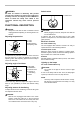
Use a screwdriver to remove the brush holder caps. Take out the worn carbon brushes, insert the new ones and secure the brush holder caps. 1. Clamp screw (A) 2. Adjusting screw 3. Clamp screw (B) 4. Trimmer guide 5. Wing bolt 1 2 1 3 4 1. Screwdriver 2. Brush holder cap 2 5 002012 Install the trimmer guide on the tool base with the clamp screw (A). Loosen the clamp screw (B) and adjust the distance between the bit and the trimmer guide by turning the adjusting screw (1 mm per turn).
Drill point flush trimming bit Trimmer bits Straight bit 005120 005116 mm D mm D 20 6 20E 1/4" 8 6 8E 6 1/4" 6 6E 1/4" A L1 L2 20 50 15 8 50 18 6 50 18 6 6 6E 1/4" A L1 L2 L3 6 60 18 28 006487 Drill point double flush trimming bit 006485 "U"Grooving bit 005121 6 6E R D A L1 L2 L3 mm L4 6 1/4" 6 70 40 12 14 006488 005117 Corner rounding bit mm D 6 6 6E 1/4" A L1 L2 R 6 60 28 3 006486 "V"Grooving bit 005125 mm D 005118 mm D A L1 L
Ball bearing corner rounding bit Chamfering bit 005126 005131 mm D A L1 L2 L3 6 23 6 20 46 11 6 50 13 5 6 20 49 14 2 60 mm R 30 D 6 A1 15 A2 8 L1 37 L2 7 L3 3.5 45 6 21 21 8 8 40 10 3.5 3 6 40 10 3.
Ball bearing cove beading bit 005134 D mm R A1 A2 A3 A4 L1 L2 L3 6 20 18 12 8 40 10 5.5 3 6 26 22 12 8 42 12 5 5 006469 Ball bearing roman ogee bit 005135 D A1 6 20 6 26 A2 L2 L3 8 L1 40 10 8 42 12 mm R2 4.5 R1 2.5 4.5 4.5 3 6 006470 NOTE: • Some items in the list may be included in the tool package as standard accessories. They may differ from country to country.
Makita Corporation Anjo, Aichi, Japan 884438E221 16 www.makita.