GB Cordless Jig Saw Instruction Manual F Scie sauteuse sans fil Manuel d’instructions D Akku-Stichsäge Betriebsanleitung I Seghetto alternativo a batteria Istruzioni per l’uso NL Snoerloze figuurzaag Gebruiksaanwijzing E Sierra de cacadora a batería Manual de instrucciones P Serra de vaivém a bateria Manual de instruções DK Akku-pendulstiksav Brugsanvisning S Sladdlös sticksåg Bruksanvisning N Batteridrevet løvsag Bruksanvisning SF Akkukäyttöinen kuviosaha Käyttöohje GR Ασύρµατο
1 3 4 5 2 1 2 6.
17 4 15 16 9 13 18 10 19 11 12 13 14 5 21 4 13 20 15 16 3
23 4 24 15 25 22 17 18 28 26 13 27 13 19 20 28 29 21 22 30 31 23 4
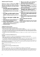
ENGLISH Explanation of general view 1 2 3 4 5 6 7 8 9 Button Battery cartridge Loosen Hex wrench Bolt Jig saw blade Roller The end of the blade shank should reach the bottom of the inner slit.
SPECIFIC SAFETY RULES 8. GEB016-1 DO NOT let comfort or familiarity with product (gained from repeated use) replace strict adherence to jig saw safety rules. If you use this tool unsafely or incorrectly, you can suffer serious personal injury. 1. Hold power tools by insulated gripping surfaces when performing an operation where the cutting tool may contact hidden wiring or its own cord. Contact with a "live" wire will make exposed metal parts of the tool "live" and shock the operator. 2. 4. 5. 6. 7.
Selecting the cutting action (Fig. 6) This tool can be operated with an orbital or a straight line (up and down) cutting action. The orbital cutting action thrusts the blade forward on the cutting stroke and greatly increases cutting speed. To change the cutting action, just turn the lever to the desired cutting action position. Refer to the table below to select the cutting action.
Cutouts (Fig. 12 & 13) Cutouts can be made with either of two methods A or B. A) Boring a starting hole: For internal cutouts without a lead-in cut from an edge, pre-drill a starting hole more than 12 mm in diameter. Insert the blade into this hole to start your cut. B) Plunge cutting: You need not bore a starting hole or make a lead-in cut if you carefully do as follows. 1. Tilt the tool up on the front edge of the base, with the blade point positioned just above the workpiece surface. 2.
NEDERLANDS Verklaring van algemene gegevens 1 2 3 4 5 6 7 8 9 Knop Accu Losdraaien Inbussleutel Bout Figuurzaagblad Rol Het uiteinde van de zaagbladschacht moet de bodem van de binnenste sleuf raken Hendel 10 11 12 13 14 15 16 17 18 19 20 Snelheidsregelknop Ontgrendelknop Trekschakelaar Gereedschapsvoet Zaaglijn Bout Kruisvormige sleuf Rand van motorhuis Schaalverdelingen Startgaatje Antisplinterinrichting TECHNISCHE GEGEVENS Model 4331D Slaglengte ......................................................
AANVULLENDE VEILIGHEIDSVOORSCHRIFTEN BEDIENINGSVOORSCHRIFTEN Laat u NIET misleiden door een vals gevoel van comfort en bekendheid met het gereedschap (na veelvuldig gebruik) en neem alle veiligheidsvoorschriften van de decoupeerzaag altijd strikt in acht. Bij onveilig of verkeerd gebruik van het elektrisch gereedschap, bestaat de kans op ernstig persoonlijk letsel. 1.
Selecteren van de zaagactie (Fig. 6) Dit gereedschap kan met twee zaagacties worden gebruikt: Zagen in een cirkelbaan of in rechte lijn (op en neer). Tijdens zagen in een cirkelbaan, wordt het zaagblad door de zaagactie naar voren geduwd en vermeerdert de zaagsnelheid aanzienlijk. Om de zaagactie te veranderen, draait u gewoon de zaagactie-keuzehendel naar de gewenste stand. Zie de onderstaande tabel voor het selecteren van de zaagactie.
Figuren uitzagen (Fig. 12 en 13) Voor het uitzagen van figuren kunt u methode A of B gebruiken. A) Voorboren van een startgaatje: Om figuren onmiddellijk in het midden van het werkstuk uit te zagen, en dus niet vanaf de rand, moet u eerst een startgaatje met een diameter van 12 mm of meer boren. Steek het zaagblad door dit gaatje en begin dan met het zagen. Cirkelgeleider (los verkrijgbaar toebehoren) (Fig.
ENH102-4 ENGLISH ITALIANO EC-DECLARATION OF CONFORMITY We declare under our sole responsibility that this product is in compliance with the following standards of standardized documents, EN60745, EN55014 in accordance with Council Directives, 89/336/EEC and 98/37/EC.
ENH102-4 PORTUGUÊS NORSK DECLARAÇÃO DE CONFORMIDADE DA CE Declaramos sob inteira responsabilidade que este produto obedece às seguintes normas de documentos normalizados, EN60745, EN55014 de acordo com as directivas 89/336/CEE e 98/37/CE do Conselho. EUs SAMSVARS-ERKLÆRING Vi erklærer på eget ansvar at dette produktet er i overensstemmelse med følgende standard i de standardiserte dokumenter: EN60745, EN55014, i samsvar med Råds-direktivene, 89/336/EEC og 98/37/ EC.
ENG004-2-V3 ENGLISH ITALIANO For European countries only Modello per l’Europa soltanto Noise and Vibration The typical A-weighted sound pressure level is 81 dB (A). Uncertainty is 3 dB (A). The noise level under working may exceed 85 dB (A). – Wear ear protection. – The typical weighted root mean square acceleration 2 value is 9 m/s . These values have been obtained according to EN60745. Rumore e vibrazione Il livello di pressione sonora pesata secondo la curva A è di 81 dB (A).
ENG004-2-V3 PORTUGUÊS NORSK Só para países Europeus Gjelder bare land i Europa Ruído e vibração O nível normal de pressão sonora A é 81 dB (A). A incerteza é de 3 dB (A). O nível de ruído durante o trabalho pode exceder 85 dB (A). – Utilize protectores para os ouvidos – O valor médio da aceleração é 9 m/s2. Estes valores foram obtidos de acordo com EN60745. Støy og vibrasjon Det vanlige A-verktet lydtrykksnivå er 81 dB (A). Usikkerheten er på 3 dB (A). Under bruk kan støynivået overskride 85 dB (A).
Makita Corporation Anjo, Aichi Japan 884339D994