Belt Sander MODEL 9031 INSTRUCTION MANUAL S PEClFICAT10 NS Belt size 30 mm x 533 mm (1.3116" x 21") Overall length Net weight 380 mm (14-31/32") 2.1 kg (4.6 Ibs) Belt speed 200 m - 1,000 m (656 ft. 3,280 f t , ) / m ~ n . ~ * Manufacturer reserves the right t o change specifications without notice. * Note: Specifications may differ from country t o country. WARNING: For your personal safety, READ and UNDERSTAND before using. SAVE THESE INSTRUCTIONS FOR FUTURE REFERENCE.
IMPORTANT SAFETY INSTRUCTIONS (For All Tools) WARNING: WHEN USING ELECTRIC TOOLS, BASIC SAFETY PRECAUTIONS SHOULD ALWAYS BE FOLLOWED TO REDUCE THE RISK OF FIRE, ELECTRIC SHOCK, AND PERSONAL INJURY, INCLUDING THE FOLLOWING: READ ALL INSTRUCTIONS. 1. KEEP WORK AREA CLEAN. Cluttered areas and benches invite injuries. 2. CONSIDER WORK AREA ENVIRONMENT. Don't use power tools in damp or wet locations. Keep work area well lit. Don't expose power tools t o rain.
14. REMOVE ADJUSTING KEYS AND WRENCHES. Form habit of checking to see that keys and adjusting wrenches are removed from tool before turning it on. 15. AVOID UNINTENTIONAL STARTING. Don't carry tool with finger on switch. Be sure switch is OFF when plugging in. 16. EXTENSION CORDS. Make sure your extension cord is in good condition. When using an extension cord, be sure to use one heavy enough to carry the current your product will draw.
VOLTAGE WARNING: Before connecting the tool to a power source (receptacle, outlet, etc.) be sure the voltage supplied is the same as that specified on the nameplate of the tool. A power source with voltage greater than that specified for the tool can result in SERIOUS INJURY t o the user - as well as damage t o the tool. If in doubt, DO NOT PLUG IN THE TOOL. Using a power source with voltage less than the nameplate rating is harmful t o the motor. ADDITIONAL SAFETY RULES 1.
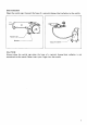
Installing the side grip For your own safety, always use the side grip. Install it by screwing it firmly on the grip holder. The side grip can be pivoted for easy operation. See the figure a t right. Side grip can pivoted - Side grip Grip holder Installing or removing the abrasive belt CAUTION : Always be sure that the tool is switched off and unplugged before installing or removing the belt. Loop the belt over the front pulley.
Switch action CAUTION : Before plugging in the tool, always check t o see that the switch trigger actuates properly and returns to the "OFF" position when released. If i t does not operate properly, do not use the tool. Have it repaired immediately. To start the tool, simply pull the trigger. Release the trigger to stop. For continuous operation, pull the trigger and then push in the lock button. To stop the tool from the locked position, pull the trigger fully, then release it.
Dust extraction Open the nozzle cap. Connect the hose of a vacuum cleaner/dust collector to the nozzle. Nozzle cap Vacuum cleaner CAUTION : Always close the nozzle cap when the hose of a vacuum cleaner/dust collector i s not connected to the nozzle. Never insert your finger into the nozzle.
MAINTENANCE CAUTION : Always be sure that the tool i s switched off and unplugged before attempting t o perform inspection or maintenance. Replacing carbon brushes Remove and check the carbon brushes regularly. Replace when they wear down to the limit mark. Keep the carbon brushes clean and free t o slip in the holders. Both carbon brushes should be replaced a t the same time. Use only identical carbon brushes. 3 Limit mark Use a screwdriver to remove the brush holder caps.
ACCESSORIES CAUTION : These accessories or attachments are recommended for use with your Makita tool specified in this manual. The use of any other accessories or attachments might present a risk of injury t o persons. The accessories or attachments should be used only in the proper and intended manner. 0 Abrasive belt (10 per pkg) Part No. 742301.
June-01 -'95 US BELT SANDER Model 9031 Note: The switch and other part configurations may differ from country to country.
MODEL 9031 June-01-'95 $zD ED MO" : ' DESCRIPTION 3 4 5 6 7 8 1 1 1 1 3 10 11 12 13 14 15 16 17 18 19 20 21 22 1 1 1 1 1 1 1 1 1 1 1 2 1 1 1 1 1 23 3 24 25 27 28 1 1 1 2 9 - DESCRIPTION MACHINE MACHINE 1 2 US ~ Grip 36 Hex Bolt Max40 Cap 30 Spring Pin 4 - 2 0 Tapping Screw 4x25 Flat Shoe Tapping Screw Bind CT 5x12 Compression Spring 13 Flat Washer 12 Wmg Nut M 1 6 Gear Housing Complete Ball Bearing 607L8 Helical Gear 35 s p m g P,n 3 5 - 12 Ball Rearing 69040DW Bearing Retainer 4 4 Tap
MAKITA LIMITED ONE YEAR WARRANTY Warranty Policy Every Makita tool is thoroughly inspected and tested before leaving the factory. It is warranted to be free of defects from workmanship and materials for the period of ONE YEAR from the date of original purchase. Should any trouble develop during this one- year period, return the COMPLETE tool, freight prepaid, to one of Makita’s Factory or Authorized Service Centers.