Angle Grinder 180 mm (7”) 230 mm (9”) MODEL 90471. MODEL 9049 INSTRUCTION MANUAL DOUBLE INSULATION No load speed (RPM) 6,000 Overall length I 470 mm (18-112“) Net weight I 4.8 kg (10.6 Ibs) Spindle thread I * Manufacturer reserves the right t o change specifications without notice. * Note: Specifications may differ from country t o country. WARNING: For your personal safety, READ and UNDERSTAND before using. SAVE THESE INSTRUCTIONS FOR FUTURE REFERENCE.
GENERAL SAFETY RULES (For All Tools) WARNING! Read and understand all instructions. Failure to follow all instructions listed below, may result in electric shock, fire and/or serious personal injury. SAVE THESE INSTRUCTIONS READ ALL INSTRUCTIONS. 1. Keep your work area clean and well lit. Cluttered benches and dark areas invite accidents. 2. Do not operate power tools in explosive atmospheres, such as in the presence of flammable liquids, gases, or dust.
11. Avoid accidental starting. Be sure switch is off before plugging in. Carrying tools with your finger on the switch or plugging in tools that have the switch on invites accidents. 12. Remove adjusting keys or switches before turning the tool on. A wrench or a key that is left attached to a rotating part of the tool may result in personal injury. 13. Do not overreach. Keep proper footing and balance at all times. Proper footing and balance enables better control of the tool in unexpected situations. 14.
Specific Safety Rules 1. Always use proper guard with grinding wheel. A guard protects operator from broken wheel fragments. 2.Accessories must be rated for at last the speed recommended on the tool warning label. Wheels and other accessories running over rated speed can fly apart and cause injury. 3.Hold tool by insulated gripping surfaces when performing an operation where the cutting tool may contact hidden wiring or its own cord.
SYMBOLS The followings show the symbols used for tool. ........................... ................................. volts amperes ................................. ................................. herts kilograms ...... .. hours ................................. minutes ....... seconds ........................... alternating current ................... direct current ................. no load speed alternating or direct current U ................................. Class II Construction ...
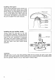
Installing wheel guard When using a depressed center wheel or an abrasive cut-off wheel, always use a wheel guard. Mount the wheel guard w i t h the tab on the wheel guard band aligned with the notch on the bearing box Then rotate the wheel guard 160 degrees counterclockwise. Be sure to tighten the screw securely. r-,-Wheel guard Installing side grip (auxiliary handle) Always install the side grip on the tool securely before operation.
Installing or removing depressed center wheel CAUTION: Always be sure that the tool is switched off and unplugged before installing or removing the wheel. Mount the inner flange onto the spindle. Fit the wheel on over the inner flange and screw the lock nut onto the spindle. To tighten the lock nut, press the shaft lock firmly so that the spindle cannot revolve, then use the lock nut wrench and securely tighten clockwise.
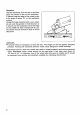
Operation Hold the tool firmly. Turn the tool on and then apply the wheel or disc to the workpiece. In general, keep the edge of the wheel or disc at an angle of about 15O to the workpiece surface. During the break-in period with a new wheel, do not work the grinder in the B direction or it will cut into the workpiece. Once the edge of the wheel has been rounded off by use, the wheel may be worked in both A and B directions. I WARN I NG: It should never be necessary to force the tool.
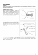
MAINTENANCE CAUTlON: Always be sure that the tool is switched off and unplugged before attempting t o perform inspection or maintenance. Replacing carbon brushes When the resin insulating tip inside the carbon brush is exposed t o contact the commutator, it will automatically shut off the motor. When this occurs, both carbon brushes should be replaced at the same time. Use only identical carbon brushes. 7 r Insulating tip Commutator 1 -Carbon brush Use a screwdriver to remove the brush holder caps.
ACCESSORIES CAUTION: These accessories or attachments are recommended for use w i t h your Makita tool specified in this manual. The use of any other accessories or attachments might present a risk of injury to persons. The accessories or attachments should be used only in the proper and intended manner. @Depressed center wheel (1 Per pkg) @Wheel guard Part No. For Model Part No.
@Abrasive disc 15 per pkgl @Rubber pad Part No. 743012-7 @Sanding lock nut 48 I I I Part No. (For abrasive disc) Part No. 22451 7-1 742067-A-5 742069-A-5 Grit 16 24 I 1 I Diameter h" 742089-A-5 180 (7") 742070-A-5 742071-A-5 80 I 742091-A-5 @Wire cup brush 120 I @Flexible grinding wheel (10 per pkg) 1-~ I Part No. Diameter lmml 743206-A Part No.
No".-01 -'96 US ANGLE GRINDER 180 mm (7") Model 9047L 230 mm (9") Model 9049 Note: The switch and other part configurations may differ from country to country.
MODEL 9047L, 9 0 4 9 F IOM DESCRIPTION 1 1 1 1 1 6 1 1 1 1 1 4 1 1 1 1 1 1 1 1 1 1 1 1 1 7 8 9 10 11 12 13 14 15 16 17 18 19 20 21 22 23 24 - 2 ': US DESCRIPTION MACHINE MACHINE 1 2 3 4 5 Nov.-01-'96 FIELD ASSEMBLY Baffle Plate Ball Bearing 6200DDW Insulation Washer ARMATURE ASSEMBLY IWith Item 3. 4 & 61 Fan 8 0 Bearing Retainer 60 Ball Bearing 63OlDDW Spiral Bevel Gear 12 Retaining Ring S-9 Tapping Screw. Flange.
MAKITA LIMITED ONE YEAR WARRANTY Warranty Policy Every Makita tool is thoroughly inspected and tested before leaving the factory. It is warranted to be free of defects from workmanship and materials for the period of ONE YEAR from the date of original purchase. Should any trouble develop during this one-year period, return the COMPLETE tool, freight prepaid, to one of Makita’s Factory or Authorized Service Centers.