GB Air Compressor Instruction manual F Compresseur d’air Manuel d’instructions D Kompressor Betriebsanleitung I Compressore Istruzioni per l’uso NL Luchtcompressor Gebruiksaanwijzing E Compresor de aire Manual de instrucciones P Compressor pneumático Manual de instruções DK Luftkompressor Brugsanvisning S Luftkompressor Bruksanvisning N Kompressor Bruksanvisning FIN Ilmakompressori Käyttöohje GR Αεροσυμπιεστής Οδηγίες χρήσης PL Kompresor powietrza Instrukcja obsługi LV
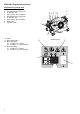
ENGLISH (Original instructions) Explanation of general view 1. 2. 3. 4. 5. 6. 7. 8. 9. Air Tank pressure gauge Regulated pressure gauge “HP” Air regulator “HP” Quick coupler “HP” (Air outlet) Regulated pressure gauge “RP” Air regulator “RP” Quick coupler “RP” (Air outlet) Drain valve Operation panel 7 4 8 10. Switch 11. Mode select switch 12. Mode LED (Blue) 2.7 - 3.5 MPa 7.0 A: Lighting 2.7 - 3.5 MPa 5.5 A: On and off light 13. Mode LED (Red) 3.1 - 3.5 MPa 7.0 A: Lighting 3.1 - 3.5 MPa 5.
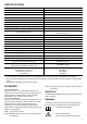
SPECIFICATIONS Model AC320H Voltage-Single Phase 220 - 240 V AC Rated current 7A Hz 50 Hz ± 1 Hz Motor Power 2 HP MAX Motor RPM 2,500 min-1 Cut-in Pressure 2.7 - 3.1 MPa (27 - 31 bar) Cut-out Pressure 3.5 MPa (35 bar) SCFM @ 100 PSIG (L/min @ 6.9 bar)* 4.4 (124 L) SCFM @ 330 PSIG (L/min @ 23 bar)* 3.6 (102 L) Bore x Stroke x Qty 62 mm x 26 mm x 1 41 mm x 10 mm x 1 Tank Size 5.
compressor it must be disconnected from the power supply. .......... Risk of high temperatures Caution: the compressor contains some parts which might reach high temperatures. .......... Risk of accidental start-up Attention, the compressor could start automatically in case of a black-out and subsequent reset. .......... Wear safety glasses. .............
RESULTING IN SERIOUS INJURY TO YOU OR OTHERS. • Failure to properly drain condensed water from the tank, causing rust and thinning of the tank wall. • Modifications or attempted repairs to the tank. • Unauthorized modifications to the pressure censor, relief valve, or any other components, which control tank pressure. • Move or transport the compressor with the air tank is filled up. HOW TO PREVENT IT • Drain air tank daily or after each use.
• Sprayed materials such as paint, paint solvents, paint remover, insecticides, weed killers etc., contain harmful vapours and poisons. • Breathing compressor or sprayed materials vapor can result in serious injury. HOW TO PREVENT IT • Never inhale air from the compressor, either directly or from breathing device connected to the compressor. Work in an area equipped with good cross ventilation.
b. Do not place compressor under inflammable, explosive or erosive service. c. Do not overturn it or lift it with hooks and ropes. DUTY CYCLE All Makita manufactured air compressor are recommended to be operated at no more than a 50% duty cycle. This means an air compressor that pumps air more than 50% of one hour is considered misuse because the air compressor is undersized for the required air demand.
least 0.3 m away from the wall or other obstructions that would interfere with the flow of air. The compressor head and shroud are designed to allow for proper cooling. If humidity is high, an air filter can be installed on the air outlet adapter to remove excessive moisture. Place the air compressor on a level surface so that it rests securely on the rubber feet. Follow the instructions packaged with the air filter for proper installation.
MAINTENANCE Air Consumption 3.1 - 3.5 MPa 7.0 A Much 2.7 - 3.5 MPa 7.0 A 3.1 - 3.5 MPa 5.5 A 2.7 - 3.5 MPa 5.5 A Little When you are finished: DISCONNECTING HOSES WARNING: Risk of unsafe operation. Firmly grasp hoses in hand when installing or disconnecting to prevent hose whip. Losing control of the hose may result in personal injury and property damage. 7. Set the switch to OFF “O”. Ensure compressor is disconnected from the main supply. NOTE: Do not stop compressor by pulling out the plug. 8.
explosion causing personal injury and property damage. 4. Inspect air lines and fittings for leaks; correct as necessary. Each year of operation or if a problem is suspected: • Check condition of air compressor pump intake and exhaust valves. • Check condition of check valve. Replace if damaged or worn out. PROBLEM 5. Keep all screws, bolts, and covers properly tightened. Check their conditions periodically. WARNING: Keep All Screws, Bolts and Covers Properly Tightened.
NEDERLANDS (Originele instructies) Verklaring van het onderdelenoverzicht 1. 2. 3. 4. 5. 6. 7. 8. 9. Drukmeter van luchttank Regeldrukmeter “HP” Luchtdrukregelaar “HP” Snelkoppeling “HP” (luchtuitlaat) Regeldrukmeter “RP” Luchtdrukregelaar “RP” Snelkoppeling “RP” (luchtuitlaat) Aftapkraantje Bedieningspaneel 1 65 9 32 7 4 8 10. Aan/uit-schakelaar 11. Functiekeuzetoets 12. Functie-LED (blauw) 2,7 - 3,5 MPa 7,0 A: Brandt 2,7 - 3,5 MPa 5,5 A: Knippert 13.
TECHNISCHE GEGEVENS Model AC320H Spanning - enkelfase 220 - 240 V AC Nominale stroomsterkte 7A Frequentie 50 Hz ± 1 Hz Motorvermogen 2 pk Maximaal motortoerental 2.
.......... Gevaar voor elektrische schokken Let op: alvorens aan de luchtcompressor te werken, moet deze worden losgekoppeld van de elektrische voeding. .......... Gevaar voor hoge temperaturen Let op: de luchtcompressor bevat onderdelen die zeer heet kunnen worden. .......... Gevaar voor per ongeluk starten Let op: de luchtcompressor kan uit zichzelf starten in het geval na een stroomstoring de elektriciteitsvoorziening wordt hersteld. .......... Draag een veiligheidsbril .............
• Gebruik nooit een transformator als elektrische voeding van de luchtcompressor. Als u een transformator gebruikt als elektrische voeding voor deze luchtcompressor, kan een storing optreden. • Als de luchtcompressor ongebruikelijk lijkt te werken, een vreemd geluid maakt of anderszins defect lijkt, stopt u onmiddellijk met het gebruik ervan en maakt u een afspraak voor reparatie door een erkend servicecentrum.
temperaturen. Gebruik de luchtcompressor nooit op vochtige of natte plaatsen. Indien gebruikt onder natte omstandigheden, kan een elektrische schok of kortsluiting ontstaan, waardoor brand kan uitbreken. HOE KUNT U DIT VOORKOMEN • Gebruik de luchtcompressor altijd in een goed geventileerde omgeving waarin geen benzinedamp of oplosmiddeldampen aanwezig zijn. • Als u ontbrandbare materialen spuit, stopt u met het gebruik van de luchtcompressor en koppelt u hem los van de hoofdvoeding.
HOE KUNT U DIT VOORKOMEN • Raak nooit hete onderdelen aan tijdens of onmiddellijk na gebruik van de luchtcompressor. Raak niets achter de beschermkappen aan en begin pas met de onderhoudswerkzaamheden nadat de luchtcompressor is afgekoeld. • Hanteren en optillen: houd de handgrepen alleen vast tijdens het verplaatsen of vervoeren van de luchtcompressor. Verplaats het gereedschap niet door het te verslepen.
BEDIENINGSPANEEL: Het bedieningspaneel is uitgerust met een aan/uitschakelaar en een functiekeuzetoets. Met de functiekeuzetoets kunt u de “INSCHAKELDRUK” van de bedrijfsfunctie en de stroomsterkte veranderen.
Raadpleeg de onderstaande tabel voor de MINIMUM vereiste voor de dikte van het verlengsnoer: Stroomsterktebereik (220 - 240 V) Totale lengte van het netsnoer 0-5A 10 m 25 ft 15 m 50 ft 20 m 75 ft 30 m 100 ft 50 m 150 ft 60 m 200 ft 1,5 mm2 1,5 mm2 1,5 mm2 2,5 mm2 4 mm2 4 mm2 mm2 mm2 mm2 mm2 4 mm2 5,1 - 8 A 1,5 8 - 12 A 2,5 mm2 1,5 2,5 2,5 mm2 Leidingen Deze luchtcompressor is niet ontworpen voor gebruik met leidingen.
Luchtverbruik 3,1 - 3,5 MPa 7,0 A Veel 2,7 - 3,5 MPa 7,0 A 3,1 - 3,5 MPa 5,5 A 2,7 - 3,5 MPa 5,5 A Weinig Nadat u klaar bent: SLANGEN LOSKOPPELEN WAARSCHUWING: Gevaar voor onveilig gebruik. Pak de slang bij het aansluiten of loskoppelen stevig in uw hand vast om een zweepslag van de slang te voorkomen. Als u de controle over de slang verliest, kan dat leiden tot persoonlijk letsel en materiële schade. 7. Zet de schakelaar in de uit-stand (“O”).
ROUTINEONDERHOUDSSCHEMA 1. Tap condenswater af uit de luchttank, eventuele vochtafscheiders en luchtfilterregelaars. 2. Controleer op ongebruikelijke geluiden en/of trillingen. 3. Controleer de druksensor om er zeker van te zijn dat deze goed werkt. WAARSCHUWING: Gevaar voor barsten. Controleer de druksensor.
De technische documentatie wordt bewaard door onze erkende vertegenwoordiger in Europa, te weten: Makita International Europe Ltd., Michigan Drive, Tongwell, Milton Keynes, Bucks MK15 8JD, Engeland De conformiteitsbeoordelingsprocedure vereist door Richtlijn 2000/14/EC was is Overeenstemming met annex VI. Officiële instantie: Société Nationale de Certification et d’Homologation s.à.r.l. (SNCH), 2a. Kalchesbruck, L-1852 LUXEMBOURG Identificatienr.