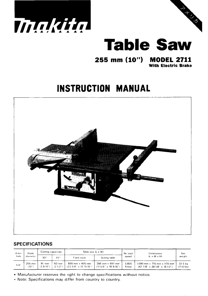
Table Saw 255 mm (10") MODEL 2711 With Electric Brake INSTRUCTION MANUAL SPEC IFI CAT I 0NS Arbor thole Blade dldnlPtel 255 m n , iio"i Table size IL x WI Cutt,ng C a P d C m e F 90" 91 m m 13 9 16'1 45" 63 nirn 'I 12 1 z Fixed table 600 m m x 405 inmi x 15 15 16 I 1 2 3 5 8' No load 295 mm x 497 mm 111 5 8 ' x 19 $ ) I 6 I Dimensions IL Sliding table 3 800 R k " 1 0 9 0 m m x 715 m m x 4 7 0 mm 142 7 < a x 2 8 im" i a i:z' I Manufacturer reserves the right to change specifications wi
For Your Own Safety Read Instruction Manual Before Operating Table Saw GENERAL SAFETY PRECAUTIONS (For All Tools) 1 KNOW YOUR POWER TOOL. Read the owner's manual carefully. Learn the tools applications and limitations, as well as the specific potential hazards peculiar t o it. 2. KEEP GUARDS IN PLACE and in working order. 3. REMOVE ADJUSTING KEYS AND WRENCHES. Form habit of checking t o see that keys and adjusting wrenches are removed from tool before turning it on. 4. KEEP WORK AREA CLEAN.
17. USE RECOMMENDED ACCESSORIES. Consult the owner’s manual for recommended accessories. The use of improper accessories may cause risk of injury t o persons. 18. NEVER STAND ON TOOL. Serious injury could occur if the tool is tipped or if the cutting tool is accidentally contacted. 19. CHECK DAMAGED PARTS.
GR 0U N D IN G INSTRUCTIONS ALL GROUNDED, CORD-CONNECTED TOOLS: In the event of a malfunction or breakdown, grounding provides a path of least resistance for electric current t o reduce the risk of electric shock. This tool is equipped w i t h an electric cord having an equipment-grounding conductor and a grounding plug. The plug must be plugged into a matching outlet that is properly installed and grounded in accordance w i t h all local codes and ordinances.
ADDITIONAL SAFETY RULES 1. Wear eye protection. 2. Don't use the tool in presence of flammable liquids or gases. 3. Never use the tool w i t h an abrasive cut-off wheel installed. 4. Check the blade carefully for cracks or damage before operation. Replace cracked or damaged blade immediately. 5. Clean the spindle, flanges (especially the installing surface) and hex nut before installing the blade. Poor installation may cause vibration/wobbling or slippage of the blade. 6.
jam the blade in the workpiece, turn the tool off immediately. Unplug the tool. Then clear the jam. 18. Never remove cut-off pieces near the blade or touch the blade guard while the blade is running. 19. Don't abuse cord. Never yank cord t o disconnect from receptacle. Keep cord away from heat, oil, water and sharp edges. SAVE THESE INSTRUCTIONS.
Movement and transport of table saw Before moving the table saw, tighten the wing bolt to secure the sliding table. When moving the table saw, hold it by the fixed table and the bars. Be sure to use two persons to lift and move it. When transporting the table saw by vehicle, secure it with a rope or other substantial means. ASSEMBLY The table saw is shipped from the factory with the ruler guides, miter gauge, saw blade, rip fence, blade guard and table insert not installed. Assemble as follows.
Installing miter gauge Insert the wooden gauge into the miter gauge and tighten the two screws lightly but firmly. The wooden gauge will be used later to help you accurately make crosscuts. Place the miter gauge on the sliding table with the wooden gauge extending toward the fixed table. Insert the longer miter gauge installation screw through the hole (A) in the miter gauge and screw it into the threaded hole in the sliding table.
Install the blade between the two flanges. Then install the outer flange and hex nut onto the arbor, making sure the teeth of the blade are pointing down a t the front of the table. To secure the blade in place, hold the outer flange with the offset wrench, then tighten the hex nut counterclockwise with the wrench. When tightening the hex nut, the offset wrench handle should be supported by the table as shown in the figure. BE SURE TO TIGHTEN THE HEX NUT SECURELY.
Installing and adjusting rip fence Loosen the lever on the rip fence and f i t the rip fence on the ruler guides. Lever Rip fence Ruler guide To check to be sure that the rip fence is parallel with the blade, secure the rip fence 2 - 3 mm (5/64"- 1/8") from the blade. Raise the blade up to maximum elevation. Mark one of the blade teeth with a crayon. Measure the distance (A) and (B) between the rip fence and blade. Take both measurements using the tooth marked with the crayon.
Tighen the lever on the rip fence. I f the rip fence is not secure enough, leave the lever in the tightened position and tighen the screw in the hole in the rear end of the rip fence clockwise. However, do not tighten the screw excessively, or the lever will become loose. I CAUTION : Be sure to adjust the rip fence parallel with the blade, or a dangerous kickback condition may occur. Move the rip fence a bit away from the blade and secure it.
Installing blade guard CAUTION : Before installing the blade guard, adjust the depth of cut to i t s maximum elevation. (Note: The depth of cut is adjusted to i t s maximum elevation when the table saw i s shipped from the factory.) Temporarily tighten the bolts with the offset wrench. Check to be sure that the blade and spreader are in a straight line. I f they are not properly aligned, shift the adjusting washers from one side to another until the spreader is aligned directly behind the blade.
Positioning table saw Locate the table saw in a well lit and level area where you can maintain good footing and balance. It should be installed in an area that leaves enough room to easily handle the size of your workpieces. The table saw should be secured with four screws or bolts to the work bench or table saw stand (optional accessory) using the holes provided in the bottom of the table saw.
Hand tool storage pocket The table saw comes with a hand tool storage pocket in the base. Keep wrenches, screwdriver, etc. in this pocket. I Adjusting depth of cut The depth of cut may be adjusted by turning the knob. Turn the knob clockwise to raise the blade or counterclockwise to lower it. The depth of cut i s indicated on the scale by the pointer (A). If the knob does not turn easily, loosen the two adjusting screws on the inside of the table saw counterclockwise.
Bevel cutting Loosen the lock lever clockwise, then tilt the blade by swinging the knob until it reaches the desired angle ( 0 to 45 degrees). The bevel is indicated on the scale by the pointer (B). After obtaining the desired angle, tighten the lock lever counterclockwise to secure the adjustment. CAUTION : After adjusting the bevel, be sure to tighten the lock lever securely. Adjusting stopper plate Secure the lock lever a t the position where the lock lever contacts the stopper plate.
Adjusting miter angle Loosen the miter gauge installation screws and adjust the miter gauge to the desired angle (0 to 45 degrees). Then tighten the miter gauge installation screws securely. CAUTION : After adjusting the miter angle, be sure to tighten the miter gauge installation screws securely. Switch action To start the tool, press the "ON" button while the key is pressed in. Press the"0FF" button to stop.
Operation CAUTION : *Make sure the blade guard works smoothly and properly for making both square cuts and bevel cuts before operation. *Never withdraw the workpiece while the blade i s running. I f you must withdraw the workpiece before completing a cut, first switch the tool off while holding the workpiece firmly. Wait until the blade has come to a complete stop before withdrawing the workpiece. Failure to do so may cause dangerous kickback.
Push block Use a 19 mm (3/4") piece of plywood. 120 . mm Faceledge parallel (5") (5") 6 mm (1/4"l 5o mm (2") Handle should be in center of plywood piece. Fasten with glue and wood screws as shown. Small piece 9.5 mm x 8 mm x 50 mm (3/8"x 5/16" x 2") of wood must always be glued to plywood to keep the blade from dulling if the operator cuts into push block by mistake. (Never use nails in push block.) Auxiliary fence Make auxiliary fence from 9.5 mm (3/8") and 19 mm (3/4")plywood pieces.
Crosscutting CAUTION : When making a crosscut, remove the rip fence from the table. When cutting long or large workpieces, always provide adequate support to the sides of the table. The support should be a t the same height as the table. (1; Loosen the wing bolt securing the sliding table. 0)Adjust the blade to 90 degrees to the table surface. Adjust the miter gauge to 0 degree. Switch the tool on and move the sliding table forward to cut the wooden gauge.
The wooden gauge cannot be used for miter cutting. NOTE: Miter cutting capacity is less than crosscutting capacity. Make sure of the max miter cutting capacity before operation. The following reference table indicates some examples of miter cutting capacity.
When a spacer block can be placed between the miter gauge and workpiece, you can obtain a greater miter cutting capacity. Ripping CAUTION When ripping, remove the miter gauge from the sliding table. .When cutting long or large workpieces, always provide adequate support behind the table. The support should be a t the same height as the table. Before operating the table saw, check to be sure that the antikickback fingers operate properly. Turn the tool off and unplug it.
i) When the width of rip i s 150 mm (6") and wider, carefully use your right hand to feed the workpiece. Use your left hand to hold the workpiece in position against the rip fence. ii) When the width of rip i s 65 mm 150 mm (2-1/2" - 6") wide, use the push stick to feed the workpiece. iii) When the width of rip is narrower than 65 mm (2-1/2"), the push stick cannot be used because the push stick will strike the balde guard. Use the auxiliary fence and push block.
Feed the workpiece by hand until the end is about 25 mm ( I ” ) from the front edge of the table. Continue to feed using the push block on the top of the auxiliary fence until the cut is complete.
MA1NT ENANCE CAUTION : Always be sure that the tool is switched off and unplugged before attempting to perform inspection or maintenance. Cleaning Clean out sawdust and chips from time to time. Carefully clean the balde guard and moving parts inside the table saw. Lubrication To keep the table saw in tip-top running condition, and to assure maximum service life, oil or grease the moving parts and rotating parts from time to time. Use machine oil #I20 to wet the felt on the slide table and the bars.
ACCESSORIES CAUTION : These accessories or attachments are recommended for use with your Makita tool specified in this manual. The use of any other accessories or attachments might present a risk of injury to persons. The accessories or attachments should be used only in the proper and intended manner Dado head set (Part No 191794-9) A dado is cutting a rabbet or a wide groove into the workpiece. The dado head set consists of two outside cutters, five inside cutters and three rings.
@ Use the chart below to select the proper cutters to obtain the various cutting widths. Flange Outslde cutter Ring ,',~~~e cutter I -*+tI I 114" I I 5116" I I I 1 0 x 2 7/16" 112" 0 9/16" I I o x 3 518" I o 11116" 0 314" 13116" 0 0 1 0 x 4 0 0 0 CAUTION : For a 1/8" cut width, the outside cutter is assembled to the spindle in the same manner as the saw blade. The outer flange must be used for each cut width.
When installing two outside cutters without any inside cutter, be sure that the cutter tips do not face each other. 0 X @ While tightening the hex nut, be careful to maintain the even spacing between the tips of the inside cutters. @ When cutting 1/2" or narrower grooves, use the table insert originally installed on the table saw. When cutting 9/16" or wider, use optional accessory table insert (Part No. 343396-9). Be sure to install proper table insert.
Featherbords are used to keep the workpiece in contact with the rip fence and table as shown, and to stop kickbacks. To install featherbords. proceed as follows : @ Turn the tool off and unplug it. @ Add 8" high flat facing board to the rip fence, the full length of the rip fence.
Ring (Part No. 257137-6) When cutting groove 1/4", 5/16", 3/8", 7/16", 1/2", 9/16" or 5/8", use this ring or rings. Table insert (Part No. 343396-9) When cutting grooves 9/16" or wider, use this table insert instead of the standard table insert. Table saw stand (Part No. STEX 122251 1 Place the stays on a level location and assemble the legs inside. Secure with the bolts and nuts, then attach the rubber caps to the ends of the legs.
Saw blades 0 Chisel tooth combination saw blade For rip and cross-cut work. Most frequently used for general carpentry. Hole Part No. 255-7A 0 I 255 (10") I 518'' I 36 1 792317-2 Carbide-tipped saw blade Fastest, smoothest longer sawing without blade sharpening cuts wood, drywall, plastic, hardwood, etc. Hole Part No. I 255-11F 0 Ruller guide F Part No. 331308-4 Rip fence Part No 122328-7 0 !Screwdriver 2 Part No. 783002-8 0 Offset wrench 1 3 - 2 2 Part No.
Holder set (Part No. 191773-7) Convenient to attach for better support of long workpieces. Attach the holder to the reverse side of the I I CAUTION : Never attempt to lift or move the table saw while holding the holders. When moving the table saw, hold it by the fixed table and the bars. Hood set (Part No. 191793-1) When you wish to maintan clean operations through easy dust collection, connect the vacuum cleaner (Makita Model 410) t o the table saw using this hood.
Jan 255 mm (IO") TABLE SAW Model 2711 32 2 2 ' 8 7 US
Note.
Jan MODEL 2711 $FD sD DESCRIPTION DESCRIPTION MACHINE ~ 2 3 4 5 6 7 8 9 IO 11 12 13 14 15 16 17 18 19 20 21 22 23 24 26 27 28 29 30 31 32 33 34 35 36 37 38 39 40 41 42 43 44 45 46 47 48 49 50 51 52 53 54 55 56 57 58 59 60 61 62 63 64 ~ 2 1 2 2 4 1 1 1 1 1 1 1 2 1 1 1 1 1 1 1 1 1 1 1 1 7 1 2 1 4 4 1 1 1 2 1 1 1 1 1 1 1 1 1 1 1 1 1 1 2 1 1 2 1 1 1 1 1 1 1 1 2 1 - Hex Bolt M 5 r 6 5 [With Washer] Rubber Pin 4 Brush Holder Cap Carbon Brush Pan Head Screw M5x40 [With Washerl PO" Motor Housing Flat W
MAKITA LIMITED ONE YEAR WARRANTY Warranty Policy Every Makita tool is thoroughly inspected and tested before leaving the factory. It is warranted t o be free of defects from workmanship and materials for the period of ONE YEAR from the date of original purchase. Should any trouble develop during this one-year period, return the COMPLETE tool, freight prepaid, t o one of Makita’s Factory or Authorized Service Centers.