
Instruction manual


12
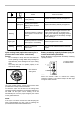
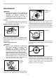
Indicator lamps
Lighted Off Blinking
EF
Remaining capacity
70% to 100%
45% to 70%
20% to 45%
0% to 20%
Charge the battery.
The battery may have
malfunctioned.
011713
•
When only the lowermost indicator lamp (next to
the "E") blinks, or when none of the indicator
lamps light, the battery capacity has run out, so
the tool does not operate. In these cases, charge
the battery or replace the empty battery with a fully
charged one.
• When two or more indicator lamps do not light
even after charging is complete, the battery has
reached the end of its service life.
• When the upper two and lower two indicator lamps
light alternately, the battery may have
malfunctioned. Contact your local Makita
authorized service center.
NOTE:
• The indicated capacity may be lower than the
actual level during use or immediately after using
the tool.
• Depending on the conditions of use and the
ambient temperature, the indication may differ
slightly from the actual capacity.
ASSEMBLY
WARNING:
• Always be sure that the tool is switched off
and battery cartridge is removed before
carrying out any work on the tool. Failure to
switch off and remove the battery cartridge may
result in serious personal injury from accidental
start-up.
• Never start the tool unless it is completely
assembled. Operation of the tool in a partially
assembled state may result in serious personal
injury from accidental start-up.
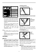
Installing the handle
For model BBC231U,BC231UD
1
3
2
012456
Insert the shaft of the handle into the grip as shown.
Align the screw hole in the grip with the one in the shaft.
Tighten the screw securely.
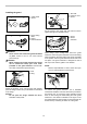
1
2
3
4
011485
Loosen knob.
Place handle between handle clamp and handle holder.
Adjust the handle to an angle that provides a
comfortable working position and then secure by firmly
hand-tightening knob.
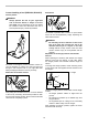
For model BBC300L,BC300LD
3
1
2
4
013123
Fit the barrier and grip onto the shaft pipe with four
screws. Make sure that the grip/barrier assembly is
fitted between the spacer and the arrow mark.
Position the barrier on the left side of the tool. Then
tighten four screws so that the grip/barrier assembly
cannot move or rotate on the shaft pipe.
WARNING:
• Do not remove or shrink the spacer. The spacer
keeps a certain distance between both hands.
Setting the grip/barrier assembly close to the other
grip beyond the length of the spacer may cause
loss of control and serious personal injury.
1. Barrier
2. Grip
3. Spacer
4. Arrow mark
1. Knob
2. Handle clamp
3. Handle holder
4. Compression
spring
1. Grip
2. Handle
3. Screw