
Operation Manual


8
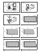
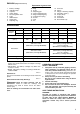
Adjusting the fastening torque (Fig. 7 & 8)
When you wish to drive machine screws, wood screws,
hex bolts, etc. with the predetermined torque, adjusting
the fastening torque as follows.
1. First remove the battery cartridge from the tool.
2. Loosen the screws securing the light cover.
3. Rotate the ring in the front of the tool by hand so that a
hole can be seen below the ring.
4. Place the battery cartridge in place and pull the switch
trigger. Release it so that the adjusting ring rotates
and becomes visible in the hole. And then remove the
battery cartridge.
5. Use an optional adjusting grip to adjust the fastening
torque. Insert the pin of the adjusting grip into the hole
in the front of the tool. And then, turn the adjusting grip
clockwise to set a greater fastening torque, and coun-
terclockwise to set a smaller fastening torque.
6. Align the edge of the adjusting ring with your desired
number on the fastening torque scale.
7. Insert the battery cartridge and be sure that a fasten-
ing torque has been set up by using a fastening torque
tester.
8. Tighten the screws to secure the light cover and then
rotate the ring in front of the tool until the ring is
locked.
NOTE:
• Numbers on the fastening torque scale is a guideline to
set up your desired fastening torque.
ASSEMBLY
CAUTION:
• Always be sure that the tool is switched off and the bat-
tery cartridge is removed before carrying out any work
on the tool.
Selecting correct socket or screw bit
There are different types of sockets or bits for some mod-
els depending on applications. Choose and install a cor-
rect socket or bit for your application.
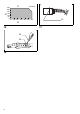
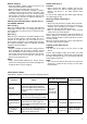
Installing or removing socket (Fig. 9)
To install the socket, push it onto the square drive of the
tool with one hand by depressing a pin on the square
drive with another hand until it locks into place. To
remove the socket, simply pull it off depressing the pin on
the square drive.
Installing or removing bit (Fig. 10)
For tools with retracting sleeve
To install the bit, pull the sleeve in the direction of the
arrow and insert the bit into the sleeve as far as it will go.
Then release the sleeve to secure the bit.
To remove the bit, pull the sleeve in the direction of the
arrow and pull the bit out firmly.
For tools without retracting sleeve
To install the bit, just insert the bit into the spindle as far
as it will go. To remove the bit, pull the bit out firmly.
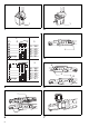
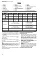
Function Status
Status of
the LED indicator/beeper
Action to be taken
LED indicator Beeper
Checking the
remaining battery
capacity,
Autostop
This function works when the battery
power is almost used up. At this time,
tool stops immediately.
Lights up in
red.
A long beep
Replace the battery
with fully charged
one.
Check the LED
indicator, light and
beeper operation
This function works to check the proper
operation of the LED indicator, light
and beeper when a battery cartridge
has been inserted into the tool.
Lights up first
in green, next
red.
(And then the
light comes
on.)
A series of
very short
beeps
__
Anti-reset of
controller
This function works when an abnormal
drop of the battery voltage occurs for
some reason, and the tool stops.
Flickers in red
and green
alternatively.
A series of
short beeps
Replace the battery
with fully charged
one.
Overheat
This function works when the tempera-
ture of the controller goes up very
highly, and the tool stops.
Flickers in red
quickly.
A series of
short beeps
Remove the battery
cartridge immedi-
ately and cool the tool
down.
Operation error of
the switch trigger
This function works to avoid the tool’s
immediate start upon insertion of bat-
tery cartridge into the tool with the
switch trigger being pulled.
Flickers in red
and green
alternatively.
A series of
short beeps
Release the switch
trigger.