REPAIR MANUAL BHX2500 BHX2500CA PB-251.
CONTENTS Ⅰ.SPECIFICATIONS・・・・・・・・・・・・ 1.SPECIFICATIONS・・・・・・・・・・・・・・・・ 2.PART NAMES・・・・・・・・・・・・・・・・・・ Ⅱ.PREPARATIONS・・・・・・・・・・・・・ 2 2 3 4 1.PREPARATIONS・・・・・・・・・・・・・・・・・ 4 2.NOTICE・・・・・・・・・・・・・・・・・・・・ 4 3.SPECIAL TOOL FOR DISASSEMBLY・・・・・・・・・ 4 Ⅲ.DISASSEMBLY AND REASSEMBLY PROCEDURE・ 5 1.EQUIPMENT DISASSEMBLY ・・・・・・・・・・・・ 5 2.EQUIPMENT REASSEMBLY・・・・・・・・・・・7~11 3.ENGINE DISASSEMBLY・・・・・・・・・・・・・・12 4.ENGINE REASSEMBLY ・・・・・・・・・・・13~25 5.CARBURETOR DISASSEMBLY AND REASSEMBLY ・26~27 6.
Ⅰ.SPECIFICATIONS 1.SPECIFICATIONS SPECIFICATIONS Product Name Engine Blower Type BHX2500/PB250.4 Dimensions(LXWXH) mm Dry Weight kg 350×231×368(13.8×9.1×14.5 in 4.5(9.5 lbs EH025F Type Air-Cooled, 4-Stroke, Upright Single-Cylinder OHV Gasoline Engine Fuel Fuel Tank Capacity Engine only for body) Model Piston Displacement mL 24.5(1.49 cu,in) Automotive Unleaded Gasoline L Engine Oil 0.52(17.6 fl.
2.PART NAMES Optional DESIGNATION OF PARTS Optional (Vacuum Set) DESIGNATION OF PARTS DESIGNATION OF PARTS DESIGNATION OF PARTS 1. Stop switch 8. Fuel Tank 15. Plug Cover 22. Vacuum Pipe A 2. Main Handle 9. Fuel Tank Cap 16. Spark Plug 23. Vacuum Pipe B 3. Trigger Lever 10. Muffler 17. Oil Cap 24. Vacuum Pipe C 4. Primer Pump 11. Assist Handle 18. Blower Tube 25. Arrow Mark 5. Air Cleaner Cover 12. Cruise lever 19. Blower Nozzle A 26. Dust Bag 6. Choke Lever 13. Screw 20.
Ⅱ.PREPARATIONS 1.PREPARATIONS (1)Workbench (2)Tool for disassembly and reassembly (3)Wash-pan (4)Wash oil (light oil, gasoline, etc) (5)Automotive 4-stroke engine oil, grease (6)Liquid packing (7)File, sand paper (8)Waste 2.NOTICE (1) Use the standard tools properly. (2) While disassembling the engine blower, memorize the locations of individual parts so that they can be reassembled correctly. Attach a tag to a part you are uncertain about its mounting position.
Ⅲ.DISASSEMBLY AND REASSEMBLY PROCEDURE 1.EQUIPMENT DISASSEMBLY Step Part of remove Procedure Fastener PCS Keep contamination or dust off the CAP,OIL and gauge. 1)Unscrew the CAP,OIL. 1 Notice ENGINE OIL 2)Drain the engine oil. 3)Screw the CAP,OIL onto the oil tank. 1)Drain the fuel. 2 FUEL 1)Remove the COVER,AIR CLEANER. 3 COVER,AIR CLEANER 4 COVER,ENGINE The fuel will spout if the fuel tube is removed with the fuel tank filled with fuel. 2)Remove the fuel tube.
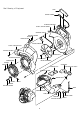
Deal Drawing of Equipment GRIP SWITCH COMPL RUBBER,FRICTION CASE 2,VOLUTE COMPL CONTROL CABLE TAPPING SCREW SPRING LEVER,CRUISE LEVER,THROTTLE CASE 1,VOLUTE ASSY TAPPING SCREW SCREW ASSY SNAPRING,OUTER PROTECTOR SCREW ASSY IMPELLER COMPL GASKET SCREW GUARD,OIL COVER,PLUG CAP,TANK FUEL ASSY TAPPING SCREW SCREW ASSY SPRING WASHER SHAFT TAPPING SCREW TUBE COVER,ENGINE TANK,FUEL WASHER HOSE CLAMP TAPPING SCREW FILTER 6
2.EQUIPMENT REASSEMBLY Equipment reassembly procedure 1.Notice ・ Clean parts completely. ・ Replace screws with new ones if necessary. ・ Tighten up the tightening torque specified parts according to the specified tightening torque. 2.Tightening torque of each part. No.
NO. 1 Part name TANK,FUEL ∼CASE 2,VOLUTE Assembling Instructions (1) Fix the fuel tank to the CASE 2,VOLUTE at the ears at the bottom of the casing. (2) Each of the tapping screws needs a washer to be set. WASHER CASE 2,VOLUTE TANK,FUEL TAPPING SCREW 5X16(3pcs) Setting of washer +5 Tightening torque 20 0 ㎏・㎝ 2 ENGINE ∼CASE 2 VOLUTE ∼IMPELLER ∼RUBBER,FRICTION (1) Fix the engine to the CASE 2,VOLUTE with the knock positions united.
NO. 3 Part name STOP SWITCH ∼CONTROL CABLE ∼LEVER,THROTTLE Assembling Instructions (1) Put off an COVER,AIR CLEANER. (2) Connect the lead wires of the STOP SWITCH with the corresponding lead wires of the COIL. Let the former lead wires through the hole of the CASE 2,VOLUTE and the STOP SWITCH terminals. Let the latter lead wires (the black one above and red one below) through the helical groove at the INSULATOR. Set the terminals downward.
NO. 4 Part name PROTECTOR ∼CASE 1,VOLUTE Assembling Instructions CASE 1,VOLUTE SCREW WASHER SNAPRING, OUTER PROTECTOR SPRING TAPPING SCREW 5X16(1pc) WASHER Tightening torque 20 +5 0 ㎏・㎝ 5 CASE 1,VOLUTE ∼CASE 2,VOLUTE SHAFT (1) Fix the CASE 1,VOLUTE to the CASE 2,VOLUTE according to the order shown below. Be sure to place the ribs of the CASE 1,VOLUTE under the corresponding ribs of the CASE 2,VOLUTE.
NO. 6 Part name CASE 2,VOLUTE ∼COVER,PLUG ∼COVER,ENGINE Assembling Instructions (1) Fix the PLUG,COVER in advance to the COVER,ENGINE. (2) Make sure that the lead wires and CONTROL CABLE are tucked in the helical groove when fixing the COVER,ENGINE. COVER,PLUG TAPPING SCREW 5X16(3pcs) +5 Tightening torque 15 0 ㎏・㎝ COVER,ENGINE SCREW ASSY M4X16(2pcs) +10 Tightening torque 15 -5 ㎏・㎝ 7 GRIP ∼GUARD,OIL (1) Fix the GRIP to the handle at the CASE 2 VOLUTE side (indicated by the arrow shown below).
3.ENGINE DISASSEMBLY Step 1 Part to remove INSULATOR Procedure 1)Remove the PLATE,AIR CLEANER. 2)Remove the breather-pipe and the return pipe from the cylinder side. 3)Remove the INSULATOR. Fastener M5X8mm PCS Notice 2 Fasten with the CARBURETOR. Use a small flat-head screwdriver for easy removal. M5X18mm M5X14mm Be sure to pull the PLATE,SWPARATOR by its body. Do not pull the PLATE,SEPARATOR by the square pipe to avoid its breakage. AIR CLEANER BREATHER 2)Remove the GASKET,SEPARATOR.
4.ENGINE REASSEMBLY Engine reassembly procedure 1.Notice ・ Clean parts completely specifically the PISTON, CYLINDER, CRANKCASE, CRANKSHAFT and BEARINGS. ・ Remove completely all the carbon deposit from the COMBUSTION CHAMBER and the PISTON top. ・ Test the lip of the OIL SEALS for damage. Replace damaged OIL SEALS with new ones. Apply oil over the lip before reassembly. ・ Replace all GASKETS with new ones. ・ Replace PINS and SCREWS with new ones if necessary.
NO. 1 2 Part name Procedure NEEDLE ROLLER BEARING (1) Apply grease over the inside of the BEARINGS and press the PIN into it. ROD LARGE AND SMALL ENDs (1) Apply 4-stroke engine oil over the PISTON RINGS and OIL RING after PISTON and placing them. CRANKSHAFT COMPL ・Position the open end of TOP RING and SECOND RING in the opposite direction.
NO. 3 Part name Procedure CYLINDER BLOCK VALVE SPRING ~RETAINER,SPRING (1) Apply 4-stroke engine oil over the inner wall of the CYLINDER, the sliding surface of the PISTON and the valve holes before reassembly. SPACER RETAINER SPRING VALVE SPRING CYLINDER BLOCK ASSY SPACER reassembling position CHECK VALVE INTAKE VALVE EXHAUST VALVE (2) Apply the oil over the valve guide hole before inserting VALVE.
NO. 4 Part name Procedure CYLINDER BLOCK ~CRANKCASE (1) Join CYLINDER BLOCK and CRANKCASE on each housing blower installation surface. CYLINDER BLOCK SET CRANKCASE COMPL SOCKET HEAD BOLT M5*14(8 pcs) Tightening torque 55±10 ㎏・㎝ <Tightening order(important)> <CRANKCASE upper side> ・Check that liquid packing (TB1216)is applied evenly over CRANKCASE(hatched surface) before reassembly.
NO. 5 Part name Procedure CRANKCASE ~CASE,OIL CASE,OIL SCREW W,SW M5*18(4 pcs) Tightening torque +10 45 -5 ㎏・㎝ TUBE,OIL WEIGHT,OIL SOCKET HEAD BOLT SW M4*10(1 pcs) Tightening torque 30~40 ㎏・㎝ GASKET,CASE RETAINER PLATE LEAD VALVE Attanch LEAD VALVE with the cut-out facing to OIL FILLER HOLE.
NO. 6 Part name Procedure FLYWHEEL (1) Degrease CRANKSHAFT and FLYWHEEL tapered portion completely before joining them. (2) Align FLYWHEEL key groove with CRANKSHAFT key. FLYWHEEL CP 7 BOLT ASSY W,SW M6*16(1 pc) Tightening torque 105±15 ㎏・㎝ (1) Attach SPRING,PLUG CAP to the HIGHT-TENSION CODE. (2) Insert the HIGHT-TENSION CODE with the SPRING,PLUG CAP into PLUG CAP. (3) Position the holes of SPRING, PLUG CAP and PLUG CAP in the same direction.
NO. 8 Part name Procedure CAMGEAR (1) Align the mark punched on FLYWHEEL(key position groove) with the timing mark on IGNITION COIL(Do not let FLYWHEEL move). timing mark (2) Join CAMGEAR to CRANKGEAR with CAM top facing down vertically (use the timing mark for reference).
NO. 9 Part name Procedure PUSH ROD CAM LIFTER ~ROCKER ARM (1) Join the CAMLIFTER to CAMGEAR. (2) Insert PUSH ROD into the PUSH ROD passage of CYLINDER. Align the PUSH ROD end with the CAM LIFTER ball groove. (3) Apply the oil over the ROCKER SHAFT hole before inserting ROCKER SHAFT.
NO. 10 Part name Procedure COVER, CAMGEAR (1) Apply the oil over the sliding surface of CAMGEAR and CAM LIFTER befor fitting COVER, CAMGEAR. SCREW ASSY W,SW M5*14(3 pcs) Tightening torque +10 45 - 5 ㎏・㎝ 11 VALVE CLEARANCE (1) Loosen NUT and adjust VALVE CLEARANCE by rotating ADJUST SCREW with a hexagon bar wrench. Adjust VALVE CLEARANCE at the compression top dead centeer(the position of the CAM top and FLYWHEEL should remain in the same one at no.9).
NO.
NO. 15 Part name Procedure INSULATOR (1) Run the lead wires, the red one down and black one up, through the upper cut-out of INSULATOR. (2) Join the red lead wire (male terminal) to the engine side (in the back). GASKET,INSULATOR The square part upward.
NO. 16 Part name Procedure CARBURETOR ~AIR CLEANER (1) Assemble PLATE,CHOKE PLATE,AIR CLEANER , PLATE , CARBURETOR GASKET,CARBURETOR , SPACER , GASKET , PIPE,BREATHER and RETURN PIPE. LEVER,CHOKE O-RING GASKET,CARBURETOR PLATE,AIR CLEANER PLATE,CHOKE GASKET PLATE CHECK VALVE(1) SCREW M5*68(2 pcs) Tightening torque +20 20 0 ㎏・㎝ PLATE,SEPARATOR COMPL O-RING PLATE,CHECK VALVE CHECK VALVE GASKET,SEPARATOR LEVER,CHOKE Keep LEVER,CHOKE fully closed when fitting PLATE,CHOKE.
NO. 17 Part name Procedure PIPE,OIL (1) Do not let O-RING remaining between the flange face of PIPE,OIL COMPL and CRANKCASE.
5.CARBURETOR DISASSEMBLY AND REASSEMBLY This engine is equipped with a diaphragm type CARBURETOR. 1)Function and structure of the diaphragm system. Since the fuel level is kept constant, in spite of any tilt angle of the engine, it can be operated at any position. The float chamber is provided with a diaphragm and covered by a cover. Negative pressure in the air intake passage causes the diaphragm to swell upward and thereby pushing up the hinge to open the valve.
3)Notice ①Clean the CARBURETOR using clean gasoline before disassembly. ②Disassemble or reassemble referring to the deal drawing. ③Do not disassemble the THROTTLE VALVE ASSY and PUMP BODY ASSY. 4)Disassembly and reassemly procedure ①Remove the screw (PUMP COVER) and then the PRIMER PUMP COVER. Remove dust clearly from the PRIMER PUMP if any. ②Remove the PUMP BODY ASSY from the body (do not let the SPRING missing). Remove dust clearly from the INLET SCREEN if any. ③Remove the JET from the body.
6. RECOIL STARTER The RECOIL STARTER rarely malfunctions under normal use. When it fails, however, or needs greasing, disassemble and reassemble it according to the following procedure. Tools:Screwdriver and pincens(pliers) 1)Disassembly (1)Remove the RECOIL STARTER from the engine. (2)Pull out the STARTER KNOB, press the ROTARY REEL with your thumb as shown in Fig.6-1 when the REEL cut-out comes to the STARTER ROPE OUTLET, and pull the STARTER ROPE to the inside of the RECOIL STARTER with a screwdriver.
2)Reassembly (1)Run the STARTER ROPE through the STARTER KNOB and make an overhand knot as showin in Fig.6-3. Run the STARTER KNOB at its opposite side from the STARTER CASE to the REEL, make a knot in the same way, and put the ROPE end completely in the ROPE HOUSING of the REEL. Then, apply a small amount of grease over the STARTER SHAFT and SPIRAL SPRING. (2)Make sure that the SPIRAL SPRING is fit completely in the spring groove of the REEL.
3)Check after reassembly (1)Pull the STARTER KNOB a few times: ①If the STARTER KNOB is too heavy to pull, check the associated parts whether they have been reassembled as instructed. ②If the RATCHET fails to function, check whether the parts such as the spring have been missing. (2)Pull the STARTER KNOB to pull out the STARTER ROPE to the end: in Fig.
IV. MALFUNCTION AND REPAIR Trouble Work order 1-1 1-2 CRANKSHAFT does not rotate. Yes 1-1 1-5 Remove the rocker cover and COVER, CAMGEAR to test the CAMGEAR, etc. for defects. No defect 1-6 1-6 Any defect in the CRANKSHAFT(bearing) Disassemble the whole engine. Breakage of the bearings of the CRANKSHAFT and ROD,CONNECTING, and/or problem such that the PISTON seizes up are likely. and/or does the PISTON seize up? 2-4 2-6 2-7 Engine does not start.
Trouble Work order 6-5 Poor acceleration and output shortage of engine Fuel 6-6 6-7 Valve train 6-8 Insufficient compression Plug and Ignition Cooling Abration and damage Oil leak from engine Engine care Correct the bad CAMGEAR timing. See PP.19~21. No 6-11 Compressed insufficiently.Return to work order 4-2 to get the proper compression in the combustion chamber. Yes 6-12 The plug ignites insufficiently.Return to work 2-3 to get the sufficient spark.
V. CHECK AND RECONDITIONING Check and recondition the engine according to the essential criteria for reconditioning after the disassembly and cleaning. the terms used in the criteria for reconditioning are described below: 1)Reconditioning To repair, adjust, replace any wrong part of the engine, so that it works like a new one.
VI. CRITERIA FOR RECONDITIONING Critera for reconditioning of EH025-type engine Part to be repaired CYLINDER BLOCK Bore diameter Inside diameter of valve guide Adjustment Adjustment accuracy limit φ34 +0.02 0.06 0 Gauge φ3 0.10 0.10 φ33.98 0 ~0.021 -0.04 -0.04 Width of ring grooves Top +0.06 +0.06 1.0 2nd 1.0 Oil 2.0 +0.04 +0.02 +0.03 +0.01 +0.03 +0.01 +0.005 -0.004 0.02L ~0.061 +0.03 +0.03 0.1 0.1 PISTON PIN hole φ8 Gap between PISTON and CYLINDER Remarks 0.06 +0.025 +0.
Part to be repaired Adjustment Adjustment accuracy limit 23.23 ±0.05 -0.6 Gauge CAMGEAR Height of cam top Shaft bore diameter φ5 +0.050 +0.010 Cam shaft diameter φ5 0 -0.010 0.010 ~0.060 Gap between CAMSHAFT and acceptance hole Usage limit Remarks Tool If not adjustable Replacement Slide calipas Replacement Inside micrometer -0.6 Micrometer Replacement Inside micrometer Replacement Intake/exhaust valve Micrometer ROCKER ARM φ3.0 φ3.0 Gap between valve shaft and valve guide Intake -0.
VII. NOTICE 1)Cleaning of air cleaner element ・Clean the element to avoid an extremely short life as well as poor start, power, and drive of the engine. ・If the oil is attached to the elements, squeeze the oil out of them. The oil attached to the elements causes the outer parts as well as the 、 air cleaner inside to be dirty by the oil. ・Remove the element(sponze), clean it with lukewarm water or mild detergent diluted by water, and dry it completely.
VIII. CARE AND STORAGE Care described below shows the standard procedure required at the correct engine use under usual conditions. Therefore, it will not give you any guarantee such that care is not necessary up to the indicated times. An air cleaner cleaning, for example, is necessary every several (not ten) hours a day during operation in a dust-laden environment.
Ⅸ.CHECK, DRAINAGE AND FEEDING OF ENGINE OIL Recommended engine oil:Auto motive oil SAE 10W-30; Class SF or higher (Automotive 4-stroke engine oil) 1.CHECK Place the equipment horizontally as shown in the figure below. Unscrew the oil gauge integrated CAP,OIL and check whether the oil level is within the upper and lower limits in the oil tank. Upper limit Upper limit Lower limit Lower limit 2.DRAINAGE Make sure that the CAP,TANK FUEL is fastened.