English BLOWER BHX2500 INSTRUCTION MANUAL Important: Read this instruction manual carefully before putting the Blower into operation and strictly observe the safety regulations! Preserve instruction manual carefully!
English Thank you very much for selecting the MAKITA blower. We are pleased to be able to offer you the MAKITA blower which is the result of a long development programme and many years of knowledge and experience. The blower models BHX2500 combines the advantages of state-ofthe-art technology with ergonomic design. They are of light weight, handy, compact and represent professional equipment for a great variety of applications.
SAFETY INSTRUCTIONS General Instructions • To ensure correct and safe operation, the user must read, understand and follow this instruction manual to assure familiarity with the handling of the blower (1). Users insufficiently informed will risk danger to themselves as well as others due to improper handling. • It is recommended only to loan the blower to people who have proven to be experienced with blowers. • Always hand over the instruction manual.
Start the Blower only in accordance with the instructions. Do not use any other methods for starting the engine (6) ! • Use the blower and the tools supplied only for applications specified. • Start the blower engine only after the entire tool has been assembled. Operation of the tool is permitted only after all the appropriate accessories are attached. • The engine is to be switched off immediately if there are any engine problems.
Method of operation • Use the blower only in good light and visibility. During cold seasons beware of slippery or wet areas, ice and snow (risk of slipping). Always ensure a safe footing. • Never work on unstable surfaces or sleep terrain. • To reduce the risk of personal injury, do not direct air blast towards bystanders, since the high pressure of the air flow could injure eyes and could blow small objects at great speed.
SPECIFICATION Model Mass (without blower pipe) BHX2500 (kg) 4.5 (9.9 lbs) Dimension (without blower pipe L x W x H) (mm) Max. engine speed ( /min) 7,800 Idling speed ( /min) 3,500 Engine displacement 350×231×368 (13.8×9.1×14.5 in) (mL) 24.5 (1.49 cu,in) Fuel Fuel tank capacity Automobile gasoline (L) SAE 10W-30 oil of API Classification, Class SF or higher (4-stroke engine for automobile) Engine oil Engine oil volume 0.52 (17.6 fl.oz) (L) 0.08 (2.7 fl.
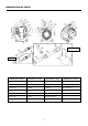
DESIGNATION OF PARTS Vacuum set (Optional) Optional DESIGNATION OF PARTS DESIGNATION OF PARTS DESIGNATION OF PARTS DESIGNATION OF PARTS 1. Stop switch 8. Fuel Tank 15. Plug Cover 22. Vacuum Pipe A 2. Main Handle 9. Fuel Tank Cap 16. Spark Plug 23. Vacuum Pipe B 3. Trigger Lever 10. Muffler 17. Oil Cap 24. Vacuum Pipe C 4. Primer Pump 11. Assist Handle 18. Blower Tube 25. Arrow Mark 5. Air Cleaner Cover 12. Cruise Control Lever 19. Blower Nozzle A 26. Dust Bag 6. Choke Lever 13.
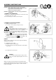
ASSEMBLY INSTRUCTIONS CAUTION : Before performing any work on the blower, always switch off the motor and pull the spark plug connectors off the spark plug. Always wear protective gloves! CAUTION : Start the blower only after having assembled it completely. 1. ASSEMBLY OF BLOWER PIPES 1) Align grooves in the blower pipe with pegs on the blower housing and slide the pipe onto housing. 2) Turn the blower pipe clockwise to lock it into place. 2.
BEFORE START OF OPERATION 1. Inspection and Refill of Engine Oil (1) Perform the following procedure, with the engine cooled down. • Inspection: Please inspect whether it makes the machine horizontal, removes the oil cap, there is a oil to inside the range of the upper limit lower limit mark of gauge. When it is insufficient, (especially, when it has not reached to the lower limit level), please refill new oil.
2. Fuel supply WARNING • When supplying the fuel, be sure to observe the following instructions to prevent ignition or fire: - Fuel supply must be made in a place free of fire. Never bring the fire (smoking, etc.) near to the place of fuel supply. - Stop the engine and allow the engine to cool down before fuel supply. - Open the fuel tank cap full of fuel slowly. The fuel may sprout out under internal pressure. - Take care not to spill the fuel. Any spilled fuel must be wiped clean.
OPERATION 1. Starting WARNING • Never attempt engine start in a place where the fuel has been supplied. - Otherwise, it will may cause ignition or fire. When starting the engine, keep a distance of at least 3 m. • Exhaust gas from the engine has toxic consequences. Do not operate the engine in a poorly-ventilated place, such as in a tunnel, building, etc. - Operating the engine in the poorly-ventilated place may cause poisoning by exhaust gas.
NOTE • The engine may be damaged if the choke lever is moved further beyond the “CLOSE” position. • If the engine stops with an explosion sound or if the engine started, but stopped before operation of the choke lever, return this lever to the “OPEN” position and pull the starter handle several times to start the engine again.
OPERATION METHOD 1. Blower operation • Hold the machine firmly during operation. • Direct the nozzle end toward the object to be dusted and pull the trigger lever. • The trigger lever can be fixed in an arbitrary position with the cruise control lever. • Maintain the trigger lever at a position where the engine speed appropriate for the operation is obtained and set the cruise control lever to the “ON” position.
INSPECTION AND MAINTENANCE DANGER • Before inspection and maintenance, stop the engine and allow it to cool. Remove also the spark plug and plug cap. - If inspection or maintenance is attempted immediately after engine stop or with the plug cap left attached, the operator may suffer burn or an accident due to careless startup. • After inspection and maintenance, be sure to confirm that all parts are assembled. Then, proceed to operation. 1.
2. Cleaning of air cleaner Plate Element (sponge) WARNING : INFLAMMABLES STRICTLY PROHIBITED Interval of Cleaning and Inspection: Daily (every 10 operating hours) (1) Remove the air cleaner cover-fixing bolts. (2) Pull the cover lower side and detach the air cleaner cover. (3) Turn the choke lever to the full close side, and keep the carburetor off from dust or dirt. (4) If oil adheres to the element (sponge), squeeze it firmly.
4. Cleaning the fuel filter • Clogged oil filter may cause difficulty of startup or failure of engine speed increase. • Check the fuel filter regularly as follows: (1) Remove the fuel tank cap, drain the fuel to empty the tank. Check the tank inside for any foreign materials. If any, wipe clean such materials. (2) Pull out the fuel filter with wire through the oil filling port. (3) If the fuel filter surface is contaminated, clean it with gasoline.
Fault location Fault System Observation Cause Engine not starting or with difficulty Ignition system Ignition spark O.K. Fault in fuel supply or compression system, mechanical defect No ignition spark STOP-switch operated, wiring fault or short circuit, spark plug or connector defective, ignition module faulty Fuel supply Fuel tank filled Incorrect choke position, carburetor defective, fuel supply line bent or blocked, fuel dirty.
TROUBLESHOOTING Before making a request for repairs, check a trouble for yourself. If any abnormality is found, control your machine according to the description of this manual. Never tamper or dismount any part contrary to the description. For repairs, contact Authorized Service Agent or local dealership. State of abnormality Probable cause (malfunction) Failure to operate primer pump Remedy Push 7 to 10 times. Low pulling speed of starter rope Pull strongly. Lack of fuel Feed fuel.
EMISSION COMPLIANCE PERIOD For handheld engine : The Emissions Compliance Period referred to on the Emissions Compliance label indicates the number of operating hours for which the engine has been shown to meet Federal emission requirements. Category C=50 hours, B=125 hours, and A=300 hours. AIR INDEX An Air Index Information hang tag was supplied to this engine in accordance with the emission regulations of the California Air Resources Board.
CALIFORNIA EMISSION CONTROL WARRANTY STATEMENT YOUR WARRANTY RIGHTS AND OBLIGATIONS The California Air Resources Board and Makita U.S.A., Inc. are pleased to explain the emission control system warranty on your 2000 and later Small Off-Road engine (herein “engine”). In California, the engine must be designed, built and equipped to meet the State's stringent anti-smog standards Makita U.S.A., Inc.
LIMITED WARRANTY on Emission Control Systems - California Only - Makita U.S.A., Inc., a distributor of Small Off-Road Engine in the U.S.
F. WHERE TO GET WARRANTY SERVICE It is recommended that warranty service be performed by the authorized dealer, who sold you the engine, although warranty service will be performed by any authorized dealers, distributors and warranty stations anywhere in the United States. When warranty repair is needed, the engine must be brought to an authorized dealer, distributorship or warranty station's place of business during normal business hours.
REPAIR AND REPLACEMENT OF EMISSION-RELATED PARTS It is recommended that only engine replacement parts which have been authorized and approved by Makita U.S.A., Inc. should be used in the performance of any warranty maintenance or repairs of emission-related parts. These replacement parts will be provided at no charge if the part is still under warranty.
FEDERAL EMISSION COMPONENT DEFECT WARRANTY EMISSION COMPONENT DEFECT WARRANTY COVERAGE - This emission warranty is applicable in all States, except the State of California Makita U.S.A., Inc., La Mirada, California, (herein "MAKITA") warrant to the initial retail purchaser and each subsequent owner, that this utility equipment engine (herein "engine" ) was designed, built, and equipped to conform at the time of initial sale to all applicable regulations of the U.S.
OBTAINING WARRANTY SERVICE To obtain warranty service, take your engine to the nearest MAKITA Factory Service Center or Service Center authorized by MAKITA. Bring your sales receipts indicating date of purchase for this engine. The dealer or service center authorized by MAKITA will perform the necessary repairs or adjustments within a reasonable amount of time and furnish you with a copy of the repair order. All parts and accessories replaced under this warranty become the property of MAKITA.
THINGS YOU SHOULD KNOW ABOUT THE EMISSION CONTROLL SYSTEM WARRANTY MAINTENANCE AND REPAIRS You are responsible for the proper use and maintenance of the engine. You should keep all receipts and maintenance records covering the performance of regular maintenance in the event questions arise. These receipts and maintenance records should be transferred to each subsequent owner of the engine. MAKITA reserves the rights to deny warranty coverage if the engine has not been properly maintained.
MEMO 27
WARNING: The Engine Exhaust from this product contains chemicals known to the state of California to cause cancer, birth defects or other reproductive harm. Makita Corporation 3-11-8, Sumiyoshi-cho, Anjo, Aichi 446-8502, Japan 6659015000 05.