
User Manual


9 ENGLISH
Lighting up the front lamp
CAUTION: Do not look in the light or see the
source of light directly.
►Fig.5: 1. Lamp
Toturnonthelamp,slightlypulltheswitchtrigger,and
thenreleaseit.Thelampgoesoutapproximately10
seconds after releasing the switch trigger.
NOTICE: When the tool is overheated, the lamp
ickers. Cool down the tool fully before operating
the tool again.
NOTE: Use a dry cloth to wipe the dirt off the lens of
the lamp. Be careful not to scratch the lens of lamp, or
it may lower the illumination.
Overload warning lamp
►Fig.6: 1. Warning lamp
Thewarninglampblinkswhenthetoolishighlyloaded.
Iftheloadincreasesandthetoolbecomesoverloaded,
the tool stops automatically and the warning lamp keeps
onlighting.Inthiscase,releasetheswitchtrigger,and
remove the cause of overload, and then restart the tool.
NOTE: When the warning lamp blinks, check the
following points:
• Thecaulkingmaterialisclogged.
• Thespeedadjustingdialissettohighspeed.
• Thecuttingareaofthetipofthecartridgenozzle
orlmtypepackageistoosmall.
Drip preventive function
Themotorkeepsrunningforashorttimeevenafterthe
triggerisreleased.Itreleasesthepressureofthecaulk-
ing material and prevents dripping.
ASSEMBLY
CAUTION: Always be sure that the tool is
switched off and the battery cartridge is removed
before carrying out any work on the tool.
Installing or removing 300 ml size
holder
Installing or removing the holder
joint
Attachtheholderjointandplatebysecuringthescrews
rmly.Toremovetheholderjoint,followtheinstallation
procedure in reverse.
►Fig.7: 1. Screw 2. Plate 3.Holderjoint
Installing or removing the rod and
piston
1. Inserttherodfromtherearsideofthetoolwithits
teeth facing down.
►Fig.8: 1. Short rod
2. Attach piston A with the screw.
►Fig.9: 1. Screw 2. Piston A 3. Short rod
NOTICE: Available type of caulking material
container for 300 ml size holder is cartridge only.
Be sure to attach piston A to the rod.
Toremovetherodandpiston,followtheinstallation
procedure in reverse.
Installing or removing the holder
CAUTION: Secure the holder to the holder
joint rmly. Otherwise the holder may come off
during operation and may cause an injury.
Toinstalltheholder,turnitclockwisermlyuntilitstops
whileholdingtheholderjoint.Toremovetheholder,
follow the installation procedure in reverse.
►Fig.10: 1. Holder
Installing or removing 600 ml or 800
ml size holder
Installing or removing the holder joint
Attachtheholderjointandplatebysecuringthescrews
rmly.Toremovetheholderjoint,followtheinstallation
procedure in reverse.
For 600 ml size holder
►Fig.11: 1. Screw 2. Plate 3.Holderjoint
For 800 ml size holder
►Fig.12: 1. Screw 2.Holderjointandplate
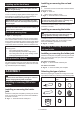
Selecting the type of piston
Select the proper type of piston according to the caulk-
ing material container by referring to the following table.
600 ml size
holder
800 ml size
holder
Cartridge
Piston A Piston D
Film package Piston B Piston E *
Directlling Piston C -
*. Optional accessary