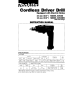
Cordless Driver Drill Equipped with Electric Brake 10 mm (3/8") MODEL 60930 10 mm (3/8") MODEL 6093DW With Fast Charger INSTRUCTION MANUAL I I SPECIF I CAT10 N S Model 6093D Capacities Steel Wood Wood screw Machine screw 10 mm 1318") I 1 Jj16"l 18 mm 5.5 mm x 55 mm 17/32" x 2-1j8"l 6 mm 115164") 96v * No load speed I Hr' I A . C . only 5 0 H z - 60Hz I High 0 ~ 1,100 Rimin. D.C 7 . 2 V - 9.6 V Dimensions IL x W x HI Low 0 - 400 Rimin.
IMPORTANT SAFETY IN STRUCTlON S (For All Tools) WARNING: WHEN USING ELECTRIC TOOLS, BASIC SAFETY PRECAUTIONS SHOULD ALWAYS BE FOLLOWED TO REDUCE THE RISK OF FIRE, ELECTRIC SHOCK, AND PERSONAL INJURY, INCLUDING THE FOLLOWING: READ ALL INSTRUCTIONS. 1 . KEEP WORK AREA CLEAN. Cluttered areas and benches invite injuries. 2. CONSIDER WORK AREA ENVIRONMENT. Don’t use power tools in damp or wet locations. Keep work area well lit. Don’t expose power tools t o rain.
14. REMOVE ADJUSTING KEYS AND WRENCHES. Form habit of checking to see that keys and adjusting wrenches are removed from tool before turning it on. 15. AVOID UNINTENTIONAL STARTING. Don't carry plugged-in tool with finger on switch. Be sure switch is OFF when plugging in. 16. OUTDOOR USE EXTENSION CORDS. When tool is used outdoors, use only extension cords intended for use outdoors and so marked. 17. STAY ALERT. Watch what you are doing, use common sense. Don't operate tool when you are tired. 18.
IMPORTANT SAFETY SAVE THESE INSTRUCTIONS - This manual contains important safety and operating instructions for battery charger. 2. Before using battery charger, read all instructions and cautionary markings o n (1) battery charger, (2) battery, and (3) product using battery. 3. CAUTION - To reduce risk of injury, charge only MAKITA Battery 7000, 9000 or 9100. Other types of batteries may burst causing personal injury and damage. 4. Do not expose charger to rain or snow. 5.
ADDITIONAL SAFETY RULES FOR CHARGER & BATTERY CARTRIDGE 1. Do not charge Battery Cartridge when temperature is BELOW 1 0 ° C (5OOF) or ABOVE 4OoC (104OF). 2. Do not attempt to use a step-up transformer, an engine generator or DC power receptacle. 3. Do not allow anything to cover or clog the charger vents. 4. Do not short the battery cartridge: (1) Do not touch the terminals with any conductive material. (2) Avoid storing battery cartridge in a container with other metal objects such a s nails, coins, etc.
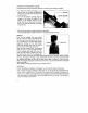
Installing or removing battery cartridge *Always switch off the tool before insertion or removal of the battery cartridge. .To remove the battery cartridge, pull out the set plate on t h e tool and grasp both sides of the cartridge while withdrawing it from the barrel. 0 To insert the battery cartridge, align t h e tongue on t h e battery cartridge with the groove in the housing and slip it into place. Snap the set plate back into place. Be sure to close the set plate fully before using the tool.
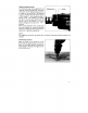
0 If you wish to charge two battery cartridges, allow 15 minutes between chargings on the fast charger. Installing or removing drill bit or driver bit CAUTION: Always be sure that the tool is switched off and the battery cartridge is removed before installing or removing the bit. To install the bit, place it in the chuck as far as it will go. Tighten the chuck by hand. Place the chuck key in each of the three holes and tighten clockwise. Be sure to tighten all three chuck holes evenly.
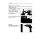
Switch action Tool speed is increased by increasing pressure on the trigger. To start the tool, simply pull the trigger. Release the trigger t o stop. CAUTION : Before inserting the battery cartridge into the tool, always check to see t h a t the trigger switch actuates properly and returns t o the "OFF" position when released. Reversing switch action This tool has a reversing switch t o change the direction of rotation.
Adjusting fastening torque The fastening torque can be adjusted in six stages by turning the adjusting ring so that the pointer on the adjusting ring points to a number on the tool body. The fastening torque is minimum when the pointer points to the number 1 and maximum when it points to the -8marking. The clutch will slip at varying torque levels when the pointer is set a t the numbers 1 to 5. The clutch is designed not to slip a t the stmarking.
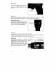
NOTE : Use the proper bit for the head of the screw that you wish to use. 0 Make sure that the driver bit is inserted straight in the screw head, or the screw and/or bit may be damaged. 0 0 When driving wood screws, predrill Pilot holes to make driving easier and to prevent splitting of t h e workpiece. See t h e chart. Nominal diameter of wood screw (mm) 3.1 (1/8") 3.5 (9/64") 3.8 (5/32") 4.5 ( 1 1 /64") 4.8 (3/16') 5.5 (7/32") I Recommended size of pilot hole (mm) 2.0 - 2.2 (5/64" - 3/32") 2.
Overload protector The overload protector automatically cuts out t o break the circuit whenever heavy work is prolonged. Wait 20 -30 seconds before resuming operation. Recycling the Battery The only way to dispose of a Makita battery is to recycle it. The law prohibits any other method of disposal. Ni-Cd To recycle a battery: 1 . Remove the battery from the tool. 2. a). Take the battery to your nearest Makita Factory Service Center or b).
MAINTENANCE CAUTION : Always be sure that the tool is switched off and the battery cartridge is removed before attempting to perform inspection or maintenance. To maintain product SAFETY and RELlABl LITY, repairs, maintenance or adjustment should be performed by Makita Authorized or Factory Service Centers, always using Makita replacement parts.
OPTIONAL ACCESSORIES The accessories listed in this manual are available at an extra cost from your Makita distributor or Makita factory service center. Service centers are listed on the warranty card packed with your tool. CAUTION : These accessories or attachments are recommended for use with your Makita tool specified in this manual. The use of any other accessories or attachments might present a risk of injury t o persons.
Dec 25-'86 EN 10 mm (318") CORDLESS DRIVER DRILL Model 6 0 9 3 D Note: The switch and other part configurations may differ from country to country.
Dec -25-'86 MODEL 6093D i\'M 1 2 DESCRIPTION 6 2 3 4 1 2 5 6 1 2 I 1 8 9 1 1 10 11 12 13 14 15 16 17 18 19 20 21 22 23 24 1 1 1 1 1 1 1 1 1 1 1 1 1 1 1 Pan Head Screw M 4 x 2 2 lWllh Washer] Pan Head Screw M 4 x 3 5 IWtth Washer1 Housing Set (With Item 441 Guide Plate c a m Plate Pan Head Screw M 5 x 1 2 Change Ring Drill Chuck S10 Pan Head Screw M 5 x 1 8 Spindle Ball Bearing 6000LLB Stop Ring E-9 Compression Spring 10 Thin Washer 10 Spur Gear 7 8 Ring 16 Spur Gear 93 Thin Washer 10 Co
MAKITA LIMED O N E YEAR WARRANTY Warranty Policy Every Makita tool is thoroughly inspected and tested before leaving the factory. It is warranted t o be free of defects from workmanship and materials for the period of ONE YEAR from the date of original purchase. Should any trouble develop during this one-year period, retum the COMPLETE tool, freight prepaid, to one of Makita’s Factory or Authorized Service Centers.