
User Manual


7 ENGLISH
NOTE: When the tool is overheated, the tool stops
automaticallyandthelampstartsashing.Inthis
case,releasetheswitchtrigger.Thelampturnsoffin
oneminute.
NOTE:Useadryclothtowipethedirtoffthelensof
thelamp.Becarefulnottoscratchthelensoflamp,or
itmaylowertheillumination.
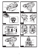
Reversing switch action
►Fig.6: 1. Reversing switch lever
CAUTION: Always check the direction of
rotation before operation.
CAUTION:
Use the reversing switch only after
the tool comes to a complete stop. Changing the direc
-
tionofrotationbeforethetoolstopsmaydamagethetool.
CAUTION: When not operating the tool,
always set the reversing switch lever to the neu-
tral position.
Thistoolhasareversingswitchtochangethedirection
ofrotation.Depressthereversingswitchleverfromthe
AsideforclockwiserotationorfromtheBsideforcoun-
terclockwise rotation.
Whenthereversingswitchleverisintheneutralposi-
tion,theswitchtriggercannotbepulled.
Speed change
►Fig.7: 1. Speed change lever
CAUTION: Always set the speed change lever
fully to the correct position.Ifyouoperatethe
toolwiththespeedchangeleverpositionedhalfway
betweenthe"1"sideand"2"side,thetoolmaybe
damaged.
CAUTION: Do not use the speed change lever
while the tool is running.Thetoolmaybedamaged.
Displayed
Number
Speed Torque Applicable
operation
1 Low High Heavy load-
ing operation
2 High Low Light loading
operation
Tochangethespeed,switchoffthetoolrst.Push
thespeedchangelevertodisplay"2"forhighspeed
or"1"forlowspeedbuthightorque.Besurethatthe
speedchangeleverissettothecorrectpositionbefore
operation.
Ifthetoolspeediscomingdownextremelyduringthe
operationwithdisplay"2",pushthelevertodisplay"1"
and restart the operation.
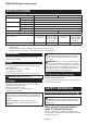
Adjusting the fastening torque
►Fig.8: 1.Adjustingring2.Graduation3.Arrow
Thefasteningtorquecanbeadjustedin21levelsbyturningtheadjustingring.Alignthegraduationswiththearrow
onthetoolbody.Youcangettheminimumfasteningtorqueat1andmaximumtorqueat
marking.
Theclutchwillslipatvarioustorquelevelswhensetatthenumber1to20.Theclutchdoesnotworkat
the marking.
Beforeactualoperation,driveatrialscrewintoyourmaterialorapieceofduplicatematerialtodeterminewhich
torquelevelisrequiredforaparticularapplication.
Thefollowingshowstheroughguideoftherelationshipbetweenthescrewsizeandgraduation.
Graduation 1 2 3 4 5 6 7 8 9 10 11 12 13 14 15 16 17 18 19 20
Machine screw M4 M5 M6
Wood
screw
Softwood
(e.g. pine)
– ɸ3.5 x 22 ɸ4.1x 38 –
Hard wood
(e.g.lauan)
– ɸ3.5 x 22 ɸ4.1x 38 –
ASSEMBLY
CAUTION: Always be sure that the tool is
switched off and the battery cartridge is removed
before carrying out any work on the tool.
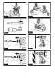
Installing or removing driver bit/
drill bit
For Model DDF483 (optional accessory)
►Fig.9: 1. Sleeve 2. Close 3. Open
Turnthesleevecounterclockwisetoopenthechuck
jaws.Placethedriverbit/drillbitinthechuckasfar
asitwillgo.Turnthesleeveclockwisetotightenthe
chuck.Toremovethedriverbit/drillbit,turnthesleeve
counterclockwise.