ENGLISH (Original instructions) INSTRUCTION MANUAL Cordless Angle Grinder DGA402 DGA450 DGA452 007214 IMPORTANT: Read Before Using.
ENGLISH (Original instructions) SPECIFICATIONS Model DGA402 Wheel diameter 100 mm Max. wheel thickness 6.4 mm Spindle thread M10 DGA450 DGA452 115 mm 6.4 mm 6.4 mm M14 or 5/8" (country specific) 11,000 (min-1) Rated speed (n) / No load speed (n0) Overall length 317 mm Net weight 2.2 kg 2.2 kg 2.3 kg Rated voltage D.C. 18 V D.C. 14.4 V D.C. 18 V • Due to our continuing program of research and development, the specifications herein are subject to change without notice.
ENG902-1 • • • • GEA006-2 The declared vibration emission value has been measured in accordance with the standard test method and may be used for comparing one tool with another. The declared vibration emission value may also be used in a preliminary assessment of exposure. The declared vibration emission value is used for main applications of the power tool. However if the power tool is used for other applications, the vibration emission value may be different.
the influence of drugs, alcohol or medication. A moment of inattention while operating power tools may result in serious personal injury. 11. Use personal protective equipment. Always wear eye protection. Protective equipment such as dust mask, non-skid safety shoes, hard hat, or hearing protection used for appropriate conditions will reduce personal injuries. 12. Prevent unintentional starting.
3. 4. 5. 6. 7. 8. 9. 10. wiring. Contact with a "live" wire will also make exposed metal parts of the power tool "live" and could give the operator an electric shock. 11. Never lay the power tool down until the accessory has come to a complete stop. The spinning accessory may grab the surface and pull the power tool out of your control. 12. Do not run the power tool while carrying it at your side.
wheel comes to a complete stop. Never attempt to remove the cut-off wheel from the cut while the wheel is in motion otherwise kickback may occur. Investigate and take corrective action to eliminate the cause of wheel binding. d) Do not restart the cutting operation in the workpiece. Let the wheel reach full speed and carefully re-enter the cut. The wheel may bind, walk up or kickback if the power tool is restarted in the workpiece.
21. 22. 23. 24. 25. 26. 27. 28. 29. 30. 31. 32. 33. wobbling that could indicate poor installation or a poorly balanced wheel. Use the specified surface of the wheel to perform the grinding. Do not leave the tool running. Operate the tool only when hand-held. Do not touch the workpiece immediately after operation; it may be extremely hot and could burn your skin. Observe the instructions of the manufacturer for correct mounting and use of wheels. Handle and store wheels with care.
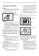
FUNCTIONAL DESCRIPTION • CAUTION: Always be sure that the tool is switched off and the battery cartridge is removed before adjusting or checking function on the tool. • Installing or removing battery cartridge 1. Button 2. Red indicator 3. Battery cartridge 1 2 In this situation, turn the tool off and stop the application that caused the tool to become overloaded. Then turn the tool on to restart. If the tool does not start, the battery is overheated.
− − Battery cartridge replacing signal − When the remaining battery capacity is low, the indicator lamp lights up during operation earlier than that of high battery capacity. Accidental re-start preventive function − Even if the battery cartridge is inserted on the tool with the slide switch in the "I (ON)" position, the tool does not start. In this situation, the lamp flickers slowly. It indicates that the accidental re-start preventive function is at work.
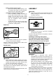
To remove wheel guard, procedure in reverse. follow the installation OPERATION Installing or removing depressed center grinding wheel/Multi-disc 1 2 3 • 1. Lock nut 2. Depressed center grinding wheel/Multi-disc 3. Inner flange • • • 007219 WARNING: Always use supplied guard when depressed center grinding wheel/Multi-disc is on tool. Wheel can shatter during use and guard helps to reduce chances of personal injury. Mount the inner flange onto the spindle.
Operation with abrasive cut-off / diamond wheel (optional accessory) 1. Lock nut 2. Abrasive cut-off wheel/diamond wheel 3. Inner flange 4. Wheel guard for abrasive cut-off wheel/diamond wheel 1 2 3 4 010855 The direction for mounting the lock nut and the inner flange varies by wheel thickness. Refer to the table below.
• • • • • • Replacing carbon brushes WARNING: When using an abrasive cut-off / diamond wheel, be sure to use only the special wheel guard designed for use with cut-off wheels. (In European countries, when using a diamond wheel, the ordinary guard can be used.) NEVER use cut-off wheel for side grinding. Do not "jam" the wheel or apply excessive pressure. Do not attempt to make an excessive depth of cut.
OPTIONAL ACCESSORIES CAUTION: These accessories or attachments are recommended for use with your Makita tool specified in this manual. The use of any other accessories or attachments might present a risk of injury to persons. Only use accessory or attachment for its stated purpose. If you need any assistance for more details regarding these accessories, ask your local Makita Service Center.
Makita Jan-Baptist Vinkstraat 2, 3070, Belgium Makita Corporation Anjo, Aichi, Japan 885268B223 www.makita.