
Parts List


Repair
P 10/ 14
[3] DISASSEMBLY/ASSEMBLY
[3]-5. Assembling of Switch knob and Switch lever (cont.)
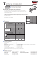
Fig. 28
Insert one end of Pin 2 into the hole of Housing L.
and put the one end of Torsion spring 2 on the rib
of Housing L. (See below for the detail.)
The other end of Pin 2 should be inserted into
the hole of Housing R.
Place the top projection on the reverse side of Switch knob
into the groove of Housing L. (See below for the detail.)
Inside view of Housing L (before assembling)
Groove
RibHole
Inside view of Housing L (after assembling)