
Parts List


ASSEMBLING
Repair
P 7/ 14
DISASSEMBLING
ASSEMBLING
Assemble by reversing the disassembly procedure.
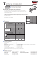
Note: When Spindle is pressfit into Spiral bevel gear 37:
1. insert the thread of Spindle into the hole of 1R034 to
receive the stepped portion of Spindle on 1R034.
2. put 1R029 on the area around the center hole of
Spiral bevel gear 37 and then press it down.
See Fig. 20.
(1) According to Fig. 13 in the previous page, remove Bearing box from Motor housing.
(2) Disassemble Shaft lock section as drawn in Figs. 21 and 22.
Fig. 20
Fig. 21
[3] DISASSEMBLY/ASSEMBLY
[3]-2. Spiral bevel gear 37, Ball bearing 696ZZ and Ball bearing 6201DDW (cont.)
[3]-3. Shaft lock section
1R029
Bearing
box
Spiral bevel
gear 37
Spindle
1R034
Arbor press
Apply 1R268 to Shoulder pin 4 through the small hole
on Pin cap and tap 1R268 with a metal hammer.
Shoulder pin 4 is removed from Gear housing.
Release 1R268 from Pin cap carefully so that Pin cap is
not slung by Compression spring 8.
Shoulder pin 4
Gear housing
Note: Remove some plastic
dust on this area before
reassembling.
Pin cap
Note: Do not re-use removed Pin cap because removal one
damages the inside surface of the cap.
Compression
spring 8
O ring 5
Small hole on Pin cap
1R268
Fig. 22
Assemble by reversing the disassembly procedure.