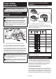
ENGLISH: Original instructions INSTRUCTION MANUAL Cordless Combination Hammer DHR280 DHR281 DHR282 DHR283 Read before use.
SPECIFICATIONS Model: DHR280 Capacities DHR281 DHR282 Concrete 28 mm Core bit 54 mm Diamond core bit (dry type) 65 mm Steel 13 mm Wood DHR283 32 mm 0 - 980 min-1 No load speed 0 - 5,000 min-1 Blows per minute Overall length 373 mm Rated voltage 404 mm 373 mm 404 mm D.C. 36 V Net weight 3.9 - 5.1 kg Optional accessory Model: DX08 (For DHR280/DHR282) Suction performance Operating stroke Up to 190 mm Suitable drill bit Up to 260 mm Rated voltage D.C.
Model DHR281 with DX09 Sound pressure level (LpA) : 92 dB(A) Sound power level (LWA) : 103 dB (A) Uncertainty (K) : 3 dB(A) Model DHR282 with DX08 Sound pressure level (LpA) : 92 dB(A) Sound power level (LWA) : 103 dB (A) Uncertainty (K) : 3 dB(A) Model DHR283 with DX09 Sound pressure level (LpA) : 92 dB(A) Sound power level (LWA) : 103 dB (A) Uncertainty (K) : 3 dB(A) Work mode: chiselling function with side grip 2 Vibration emission (ah, Cheq): 8.5 m/s Uncertainty (K) : 1.
2. 3. 4. 5. 6. 7. Avoid body contact with earthed or grounded surfaces, such as pipes, radiators, ranges and refrigerators. There is an increased risk of electric shock if your body is earthed or grounded. Do not expose power tools to rain or wet conditions. Water entering a power tool will increase the risk of electric shock. Do not abuse the cord. Never use the cord for carrying, pulling or unplugging the power tool. Keep cord away from heat, oil, sharp edges or moving parts.
Battery tool use and care 1. Recharge only with the charger specified by the manufacturer. A charger that is suitable for one type of battery pack may create a risk of fire when used with another battery pack. 2. Use power tools only with specifically designated battery packs. Use of any other battery packs may create a risk of injury and fire. 3.
. 7. 8. 9. 10. 11. 12. Do not store the tool and battery cartridge in locations where the temperature may reach or exceed 50 °C (122 °F). Do not incinerate the battery cartridge even if it is severely damaged or is completely worn out. The battery cartridge can explode in a fire. Be careful not to drop or strike battery. Do not use a damaged battery. The contained lithium-ion batteries are subject to the Dangerous Goods Legislation requirements. For commercial transports e.g.
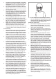
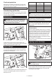
Indicating the remaining battery capacity FUNCTIONAL DESCRIPTION Only for battery cartridges with the indicator CAUTION: Always be sure that the tool is switched off and the battery cartridge is removed before adjusting or checking function on the tool. Installing or removing battery cartridge 1 CAUTION: Always switch off the tool before installing or removing of the battery cartridge. 2 CAUTION: Hold the tool and the battery cartridge firmly when installing or removing battery cartridge.
Overheat protection Number Revolutions per minute Blows per minute When the tool or battery is overheated, the tool stops automatically. In this case, let the tool and battery cool before turning the tool on again. 5 980 5,000 4 810 4,130 NOTE: When the tool is overheated, the lamp blinks. 3 640 3,260 2 470 2,400 1 300 1,550 Overdischarge protection When the battery capacity is not enough, the tool stops automatically.
Changing the quick change chuck for SDS-plus CAUTION: For DHR282/DHR283 If the lamp goes off after blinking for a few seconds, the active feedback sensing technology or the soft no-load rotation function is not working properly. Ask your local Makita Service Center for repair. For DHR281/DHR283 The quick change chuck for SDS-plus can be easily exchanged for the quick change drill chuck. NOTE: Use a dry cloth to wipe the dirt off the lens of the lamp.
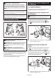
Selecting the action mode Hammering only NOTICE: Do not rotate the action mode chang- For chipping, scaling or demolition operations, rotate the action mode changing knob to the symbol. Use a bull point, cold chisel, scaling chisel, etc. ing knob when the tool is running. The tool will be damaged. NOTICE: To avoid rapid wear on the mode change mechanism, be sure that the action mode changing knob is always positively located in one of the three action mode positions.
Adjusting the nozzle position of the dust collection system Adjusting the drilling depth of the dust collection system Optional accessory Optional accessory Push in the guide while pushing up the guide adjustment button, and then release the button at the desired position. Slide the depth adjustment button to the desired position while pushing it up. The distance (A) is the drilling depth. A 1 ► 1.
Installing or removing drill bit ASSEMBLY Clean the shank end of the drill bit and apply grease before installing the drill bit. CAUTION: Always be sure that the tool is switched off and the battery cartridge is removed before carrying out any work on the tool. Side grip (auxiliary handle) 2 CAUTION: Always use the side grip to ensure safe operation. CAUTION: After installing or adjusting the side grip, make sure that the side grip is firmly secured.
Chisel angle (when chipping, scaling or demolishing) Installing or removing the dust collection system The chisel can be secured at the desired angle. To change the chisel angle, rotate the action mode changing knob to the O symbol. Turn the chisel to the desired angle. Optional accessory To install the dust collection system, insert the tool into the dust collection system all the way until it locks in place with a little double click. 1 ► 1.
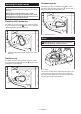
Dust cup Optional accessory Use the dust cup to prevent dust from falling over the tool and on yourself when performing overhead drilling operations. Attach the dust cup to the bit as shown in the figure. The size of bits which the dust cup can be attached to is as follows. Model Bit diameter Dust cup 5 6 mm - 14.5 mm Dust cup 9 12 mm - 16 mm 1 ► 1. Dust cap 1 To remove the dust cup set, remove the bit while pulling the chuck cover in the direction of the arrow. 1 2 ► 1.
Hammer drilling operation OPERATION CAUTION: There is tremendous and sudden twisting force exerted on the tool/drill bit at the time of hole break-through, when the hole becomes clogged with chips and particles, or when striking reinforcing rods embedded in the concrete. Always use the side grip (auxiliary handle) and firmly hold the tool by both side grip and switch handle during operations. Failure to do so may result in the loss of control of the tool and potentially severe injury.
For DHR281/DHR283 Drilling in wood or metal Use the quick change drill chuck as standard equipment. When installing it, refer to "changing the quick change chuck for SDS-plus". Hold the ring and turn the sleeve counterclockwise to open the chuck jaws. Place the bit in the chuck as far as it will go. Hold the ring firmly and turn the sleeve clockwise to tighten the chuck. CAUTION: Hold the tool firmly and exert care when the drill bit begins to break through the workpiece.
2. 1 Open the cover of the dust case. 1 2 ► 1. Dust case 2. Dial ► 1. Cover Disposing of dust 3. Optional accessory Dispose of the dust, and then clean the filter. CAUTION: Always be sure that the tool is switched off and the battery cartridge is removed before carrying out any work on the tool. CAUTION: Be sure to wear dust mask when disposing of dust. CAUTION: Empty the dust case regularly before the dust case becomes full.
The overview of the wireless activation function setting is as follows. Refer to each section for detail procedures. Using dust cup set Optional accessory 1. Installing the wireless unit Fit the dust cup set against the ceiling when operating the tool. 2. Tool registration for the vacuum cleaner 3. Starting the wireless activation function Installing the wireless unit Optional accessory CAUTION: Place the tool on a flat and stable surface when installing the wireless unit.
When removing the wireless unit, open the lid slowly. The hooks on the back of the lid will lift the wireless unit as you pull up the lid. 2. Set the stand-by switch on the vacuum cleaner to "AUTO". 1 2 1 3 ► 1. Stand-by switch 3. Press the wireless activation button on the vacuum cleaner for 3 seconds until the wireless activation lamp blinks in green. And then press the wireless activation button on the tool in the same way. ► 1. Wireless unit 2. Hook 3.
NOTE: The wireless activation lamps finish blinking in green after 20 seconds elapsed. Press the wireless activation button on the tool while the wireless activation lamp on the cleaner is blinking. If the wireless activation lamp does not blink in green, push the wireless activation button briefly and hold it down again. 4. Push the wireless activation button on the tool briefly. The wireless activation lamp will blink in blue.
Description of the wireless activation lamp status 1 ► 1. Wireless activation lamp The wireless activation lamp shows the status of the wireless activation function. Refer to the table below for the meaning of the lamp status. Status Wireless activation lamp On Standby Description Duration Color Blinking Blue 2 hours When the tool is running. Tool registration Green Red Others Red Off The wireless activation of the vacuum cleaner is available and the tool is running.
If the cancellation is performed successfully, the wireless activation lamps will light up in red for 2 seconds and start blinking in blue. Cancelling tool registration for the vacuum cleaner Perform the following procedure when cancelling the tool registration for the vacuum cleaner. 1. Install the batteries to the vacuum cleaner and the tool. 2. Set the stand-by switch on the vacuum cleaner to "AUTO". NOTE: The wireless activation lamps finish blinking in red after 20 seconds elapsed.
Troubleshooting for wireless activation function Before asking for repairs, conduct your own inspection first. If you find a problem that is not explained in the manual, do not attempt to dismantle the tool. Instead, ask Makita Authorized Service Centers, always using Makita replacement parts for repairs. State of abnormality Probable cause (malfunction) Remedy The wireless activation lamp does not light/blink. The wireless unit is not installed into the tool.
3. MAINTENANCE CAUTION: Always be sure that the tool is switched off and the battery cartridge is removed before attempting to perform inspection or maintenance. Remove the filter from the filter case. 1 NOTICE: Never use gasoline, benzine, thinner, 2 alcohol or the like. Discoloration, deformation or cracks may result.
OPTIONAL ACCESSORIES CAUTION: These accessories or attachments are recommended for use with your Makita tool specified in this manual. The use of any other accessories or attachments might present a risk of injury to persons. Only use accessory or attachment for its stated purpose. If you need any assistance for more details regarding these accessories, ask your local Makita Service Center.
Makita Europe N.V. Jan-Baptist Vinkstraat 2, 3070 Kortenberg, Belgium Makita Corporation 3-11-8, Sumiyoshi-cho, Anjo, Aichi 446-8502 Japan www.makita.