
operation manual


6
ENGLISH (Original instructions)
Explanation of general view
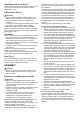
SPECIFICATIONS
• Due to our continuing program of research and development, the specifications herein are subject to change without
notice.
• Specifications and battery cartridge may differ from country to country.
• Weight, with battery cartridge, according to EPTA-Procedure 01/2003
Intended use
ENE001-1
The tool is intended for planing wood.
General Power Tool Safety
Warnings GEA010-1
WARNING Read all safety warnings and all
instructions. Failure to follow the warnings and
instructions may result in electric shock, fire and/or
serious injury.
Save all warnings and
instructions for future reference.
CORDLESS PLANER SAFETY
WARNINGS GEB064-2
1. Wait for the cutter to stop before setting the tool
down. An exposed rotating cutter may engage the
surface leading to possible loss of control and serious
injury.
2. Use clamps or another practical way to secure and
support the workpiece to a stable platform. Holding
the work by your hand or against the body leaves it
unstable and may lead to loss of control.
3. Rags, cloth, cord, string and the like should never
be left around the work area.
4. Avoid cutting nails. Inspect for and remove all
nails from the workpiece before operation.
5. Use only sharp blades. Handle the blades very
carefully.
6. Be sure the blade installation bolts are securely
tightened before operation.
7. Hold the tool firmly with both hands.
8. Keep hands away from rotating parts.
9. Before using the tool on an actual workpiece, let it
run for a while. Watch for vibration or wobbling
that could indicate poor installation or a poorly
balanced blade.
10. Make sure the blade is not contacting the
workpiece before the switch is turned on.
11. Wait until the blade attains full speed before
cutting.
12. Always switch off and wait for the blades to come
to a complete stop before any adjusting.
1. Button
2. Red indicator
3. Battery cartridge
4. Star mark
5. Pointer
6. Knob
7. Lock-off lever
8. Switch trigger
9. Planer blade
10. Rear base
11. Foot
12. Socket wrench
13. Bolt
14. Loosen
15. Tighten
16. Bolts
17. Drum
18. Drum cover
19. Adjusting plate
20. Inside edge of gauge plate
21. Blade edge
22. Screws
23. Heel
24. Back side of gauge base
25. Gauge plate
26. Gauge base
27. Pan head screw
28. Planer blade locating lugs
29. Heel of adjusting plate
30. Set plate
31. Inside flank of gauge plate
32. Back side of gauge base
33. Mini planer blade
34. Groove
35. Hex. flange head bolts
36. Nozzle
37. Dust bag
38. Fastener
39. Elbow
40. Start
41. End
42. Cutting line
43. Screw
44. Edge fence (optional accessory)
45. Sharpening holder
46. Wing nut
47. Blade (A)
48. Blade (B)
49. Side (D)
50. Side (C)
51. Limit mark
52. Chip cover
53. Screwdriver
54. Brush holder cap
Model DKP140 DKP180
Planing width 82 mm
Planing depth 1.6 mm 2 mm
Shiplapping depth 9 mm
No load speed (min
-1
) 15,000
Overall length 329 mm 333 mm
Net weight 3.3 kg 3.4 kg
Rated voltage D.C. 14.4 V D.C. 18 V