
User Manual


9 ENGLISH
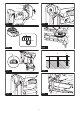
You can store the nose adapter on the holder on the
backendofthemagazinetokeepitfrombeinglost.
►Fig.10: 1. Dent 2. Protrusion 3. Nose adapter
4. Holder
Hook
CAUTION: Do not hang the hook from the
waist belt. Dropping the pin nailer, which is caused
bythehookaccidentallycomingoutofplace,may
causeunintentionalringandresultinpersonal
injuries.
►Fig.11
Thehookisconvenientfortemporarilyhangingthetool.
Thiscanbeinstalledoneithersideofthetool.
Toinstallthehook,insertitintoagrooveinthetool
housing on either side and then secure it with a screw.
Toremove,loosenthescrewandthentakeitout.
►Fig.12: 1. Groove 2. Hook 3.Screw
Hex wrench storage
When not in use, store the hex wrench as shown in the
guretokeepitfrombeinglost.
►Fig.13: 1. Hex wrench
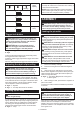
OPERATION
Testing the safety system
WARNING: Make sure all safety systems are
in working order before operation. Failure to do
so may cause personal injuries.
►Fig.14: 1.Trigger-lockbutton2.Switchtrigger
3. Contact element 4.Magazine
Testsafetysystemsforpossiblefaultbeforeoperation
asfollows.
1. Unloadpinnailsfromthetoolandkeepthemaga-
zine opened.
2. Installthebatterycartridgeandreleasethetrigger
lock.
3. Only pull the switch trigger without touching the
contact element against the material.
4. Only touch the contact element against the mate-
rial without pulling the switch trigger.
Ifthetooloperatesinthecaseof3and4above,the
safetysystemsarefaulty.Stopusingthetoolimmedi-
ately and ask your local service center.
Driving pin nails
WARNING: Continue to place the contact
element rmly on the material until the pin nail is
driven completely.Unintentionalringmaycause
personalinjuries.
1. Release the trigger lock.
2. Placeatthecontactelementonthematerial.
3. Pulltheswitchtriggerfullytodriveapinnail.
4. Todrivethenextpinnail,releaseyourngerfrom
the switch trigger once, and then repeat the step 2 and
3above.
►Fig.15: 1.Switchtrigger2. Contact element
You can also drive the pin nails when dragging the
tool to the next area with the contact element pressed
against the material and pulling the switch trigger.
►Fig.16
Iftheheadofthepinnailremainsabovetheworkpiece
surface,drivethepinnailwhileholdingthepinnailer
headrmlyagainsttheworkpiece.
►Fig.17
NOTE:Iftheheadofthepinnailstillremainsabove
the workpiece even you hold the pin nail head,
thematerialmaynotbesuitableforthepinnailer.
Continuing to use the pin nailer on such material may
resultinadamagetothedriverofthepinnailerand/
orpinnailerjamming.
Anti dry re mechanism
WARNING: Always make sure that your
ngers are not placed on the switch trigger or
the contact element and the battery cartridge is
removed before loading the pin nailer.
Whenthenumberofremainingpinnailsinthemaga-
zineare0-3pieces,theswitchtriggercannolongerbe
pulled.Atthistime,insertanewstripofpinnailsinthe
magazineandtheswitchtriggercanbepulledagain.
NOTE:Whenringadifferentlengthofpinnails
shortlyaftertheanti-dryringdevicehasactuated,
insertanewstripofpinnailsintothemagazineand
reawayallthepriorpinnailsthathaveremainedon
junkmaterial.
Checking remaining pin nails
Youcanchecktheamountofremainingpinnails
through the sight window.
Theredindicatormovestowardfasteningopeningwith
theamountofremainingpinnailsbecomesmaller.
►Fig.18: 1.Sightwindow2. Indicator
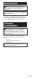
Removing jammed pin nails
WARNING: Always make sure that the battery
cartridge is removed before removing jammed
pin nails.
Takeoutpinnailsthatremaininsidethemagazine.
Remove three screws with the hex wrench that are
securing the driver guide cover.
Takethejammednailsfromthenailguidegroovethat
has appeared.
Whenitisdifculttotakeoutthejammednails,further
remove two screws with the hex wrench that are secur-
ingthecontacttopcover.Thentakethemout.
►Fig.19: 1. Driver guide cover 2.Screw3. Contact
top cover