INSTRUCTION MANUAL MANUAL DE INSTRUCCIONES Cordless Impact Driver Atornillador de Impacto Inalámbrico DT04 IMPORTANT: Read Before Using. IMPORTANTE: Lea antes de usar.
ENGLISH (Original instructions) SPECIFICATIONS Model: Fastening capacities No load speed (RPM) Impacts per minute DT04 Machine screw 4 mm - 8 mm (5/32" - 5/16") Standard bolt 5 mm - 14 mm (3/16" - 9/16") High tensile bolt 5 mm - 12 mm (3/16" - 1/2") Hard impact mode 0 - 3,000 /min Soft impact mode 0 - 1,300 /min Hard impact mode 0 - 3,900 /min Soft impact mode 0 - 1,600 /min Rated voltage D.C. 10.
4. 5. 6. 7. Remove any adjusting key or wrench before turning the power tool on. A wrench or a key left attached to a rotating part of the power tool may result in personal injury. Do not overreach. Keep proper footing and balance at all times. This enables better control of the power tool in unexpected situations. Dress properly. Do not wear loose clothing or jewellery. Keep your hair, clothing, and gloves away from moving parts. Loose clothes, jewellery or long hair can be caught in moving parts.
Important safety instructions for battery cartridge 1. 2. 3. 4. 5. 6. 7. 8. 9. 10. 11. Before using battery cartridge, read all instructions and cautionary markings on (1) battery charger, (2) battery, and (3) product using battery. Do not disassemble battery cartridge. If operating time has become excessively shorter, stop operating immediately. It may result in a risk of overheating, possible burns and even an explosion.
Overloaded: The tool is operated in a manner that causes it to draw an abnormally high current. In this situation, turn the tool off and stop the application that caused the tool to become overloaded. Then turn the tool on to restart. If the tool does not start, the battery is overheated. In this situation, let the battery cool before turning the tool on again. Switch action Low battery voltage: The remaining battery capacity is too low and the tool will not operate.
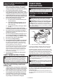
Reversing switch action 1 A ► 1 . Button B 1 Pull the switch trigger to turn on the lamp. To turn off, release it. The lamp goes out approximately 10 seconds after releasing the switch trigger. To keep the lamp off, turn off the lamp status. To turn off the lamp status, first pull and release the switch trigger. And then press the button for one second within 10 seconds. To turn on the lamp status again, press the button again similarly. ► 1 .
Impact force grade displayed on panel Maximum blows Purpose Example of application Hard 3,900 min-1 (/min) Tightening when force and speed are desired. Tightening wood screws, tightening bolts. Soft 1,600 min-1 (/min) Tightening with less force to avoid screw thread breakage. Tightening sash screws, tightening small screws such as M6. A mode 3,900 min-1 (/min) Tightening screws with better control. Tightening long screws. NOTE: A mode is available only when the tool rotates clockwise.
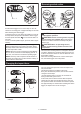
Standard bolt Installing hook N•m (ft•lbs) 120 (87) 1 2 2 3 100 (72) M14(9/16") 80 (58) M12(1/2") M14(9/16") 60 (43) M10(3/8") M12(1/2") 40 (29) ► 1 . Groove 2. Hook 3. Screw M8(5/16") M10(3/8") 20 (14) The hook is convenient for temporarily hanging the tool. This can be installed on either side of the tool. To install the hook, insert it into a groove in the tool housing on either side and then secure it with a screw. To remove, loosen the screw and then take it out.
NOTE: Use the proper bit for the head of the screw/ bolt that you wish to use. 1 NOTE: When fastening M8 or smaller screw, choose a proper impact force and carefully adjust pressure on the switch trigger so that the screw is not damaged. 2 NOTE: Hold the tool pointed straight at the screw. NOTE: If the impact force is too strong or you tighten the screw for a time longer than shown in the figures, the screw or the point of the driver bit may be overstressed, stripped, damaged, etc.
This Warranty gives you specific legal rights, and you may also have other rights which vary from state to state. Some states do not allow the exclusion or limitation of incidental or consequential damages, so the above limitation or exclusion may not apply to you. Some states do not allow limitation on how long an implied warranty lasts, so the above limitation may not apply to you.
ESPAÑOL (Instrucciones originales) ESPECIFICACIONES Modelo: Capacidades de apriete Velocidad sin carga (RPM) Impactos por minuto DT04 Tornillo de máquina 4 mm - 8 mm (5/32" - 5/16") Tornillo estándar 5 mm - 14 mm (3/16" - 9/16") Tornillo de alta resistencia 5 mm - 12 mm (3/16" - 1/2") Modo de impacto duro 0 r/min - 3 000 r/min Modo de impacto suave 0 r/min - 1 300 r/min Modo de impacto duro 0 ipm - 3 900 ipm Modo de impacto suave 0 ipm - 1 600 ipm Tensión nominal 10,8 V c.c. - 12 V (máx.
6. Si no es posible evitar usar una herramienta eléctrica en condiciones húmedas, utilice un alimentador protegido con interruptor de circuito de falla a tierra (ICFT). El uso de un ICFT reduce el riesgo de descarga eléctrica. 3. Seguridad personal 1. Manténgase alerta, preste atención a lo que está haciendo y utilice su sentido común cuando opere una herramienta eléctrica. No utilice una herramienta eléctrica cuando esté cansado o bajo la influencia de drogas, alcohol o medicamentos.
4. Advertencias de seguridad para el atornillador de impacto inalámbrico 1. 2. 3. 4. 5. 6. Sujete la herramienta eléctrica por las superficies de agarre aisladas al realizar una operación en la que el sujetador pueda entrar en contacto con cables ocultos. Si el sujetador entra en contacto con un cable con corriente, las piezas metálicas expuestas de la herramienta eléctrica se cargarán también de corriente y el operario puede recibir una descarga. Asegúrese siempre de que pisa sobre suelo firme.
Sistema de protección de batería DESCRIPCIÓN DEL FUNCIONAMIENTO PRECAUCIÓN: Asegúrese siempre de que la herramienta esté apagada y el cartucho de batería haya sido extraído antes de realizar cualquier ajuste o comprobación en la herramienta. Instalación o extracción del cartucho de batería PRECAUCIÓN: Apague siempre la herramienta antes de colocar o quitar el cartucho de batería. PRECAUCIÓN: Sujete la herramienta y el cartucho de la batería con firmeza al colocar o quitar el cartucho de batería.
NOTA: Dependiendo de las condiciones de uso y la temperatura ambiente, la indicación podrá diferir ligeramente de la capacidad real. Accionamiento del interruptor 1 ► 1 . Botón Jale el gatillo interruptor para encender la lámpara. Para apagarla, suéltelo. La lámpara se apagará aproximadamente 10 segundos después de haber soltado el gatillo interruptor. 1 Para mantener la lámpara apagada, desactive el estado de la lámpara.
Esta herramienta tiene un conmutador de inversión para cambiar la dirección de rotación. Presione la palanca del conmutador de inversión desde el lado A para una rotación en sentido de las manecillas del reloj o desde el lado B, para una rotación en sentido inverso al de las manecillas del reloj. Cuando la palanca del conmutador de inversión esté en la posición neutral, no se podrá jalar el gatillo conmutador. PRECAUCIÓN: Confirme siempre la direc- ción de rotación antes de la operación.
Instalación del gancho MONTAJE PRECAUCIÓN: Asegúrese siempre de que la herramienta esté apagada y el cartucho de batería haya sido extraído antes de realizar cualquier trabajo en la misma. Instalación o extracción de la punta de destornillador/punta de atornillar 1 2 Accesorio opcional 3 ► 1 . Ranura 2. Gancho 3. Tornillo 12 mm (15/32”) 9 mm (3/8”) El gancho resulta útil para colgar temporalmente la herramienta. Se puede instalar en cualquiera de los lados de la herramienta.
Perno estándar NOTA: Utilice la broca apropiada para la cabeza del tornillo/perno que desee utilizar. N•m (ft•lbs) NOTA: Cuando fije un tornillo de 8 mm o más pequeño, elija una fuerza de impacto apropiada y ajuste cuidadosamente la presión sobre el gatillo interruptor para evitar que el tornillo se dañe. 120 N•m (87 ft•lbs) 2 NOTA: Sujete la herramienta dirigida en línea recta al tornillo.
2. Coloque la herramienta en la funda y asegúrela con el broche de la funda. Si necesita cualquier ayuda para más detalles en relación con estos accesorios, pregunte a su centro de servicio local Makita. • Puntas de destornillador • Puntas intercambiables • Aditamento de broca • Funda • Gancho • Estuche de transporte de plástico • Batería y cargador originales de Makita NOTA: Algunos de los artículos en la lista pueden incluirse en el paquete de la herramienta como accesorios estándar.
< USA only > WARNING Some dust created by power sanding, sawing, grinding, drilling, and other construction activities contains chemicals known to the State of California to cause cancer, birth defects or other reproductive harm. Some examples of these chemicals are: • lead from lead-based paints, • crystalline silica from bricks and cement and other masonry products, and • arsenic and chromium from chemically-treated lumber.
DC10SB DC10WD GB Battery Charger............. 3 F Chargeur........................ 5 E Cargador de Batería...... 8 IMPORTANT: Read Before Using. IMPORTANT : Lire ce qui suit avant d’utiliser cet outil. IMPORTANTE: Leer antes de usar.
(DC10SB) ≧30mm ≧90mm 69mm (1-3/16”) (2-23/32”) (3-9/16”) ≧30mm (1-3/16”) ≧32mm (1-9/32”) ≧50mm (1-31/32”) ≧180mm 110mm (4-11/32”) ≧75mm (2-31/32”) (7-3/32”) ≈8mm (5/16”) ≧115mm (4-17/32”) 1 (DC10WD) ≧55mm (2-3/16”) ≧115mm (4-17/32”) ≧35mm (1-3/8”) ≧30mm ≧40mm (1-3/16”) ≧105mm (1-19/32”) 113mm (4-15/32”) 113mm (4-15/32”) ≧50mm (1-31/32”) (4-5/32”) ≧65mm (2-9/16”) 2 3 2 4 ≈4mm (5/32”)
ENGLISH Symbols The followings show the symbols used for the equipment. Be sure that you understand their meaning before use. • Indoor use only. • Read instruction manual. • DOUBLE INSULATION • Ready to charge. • Charging. • Charging complete. • Delay charge (Battery cooling, or too cold battery). • Delay charge (Too hot or too cold battery). Specification: Model Input Output Weight • Defective battery. • Cooling abnormality. • Do not short battery. • Do not destroy battery by fire.
Charging 1. 2. 3. Plug the battery charger into the proper AC voltage source. Charging light will flash in green color repeatedly. Insert the battery cartridge into charger until it stops adjusting to the guide of charger. When the battery cartridge is inserted, the charging light color will change from green to red and charging will begin. The charging light will keep lighting up steadily during charging.
Wall mounting Warning: • Make sure to use two screws for hanging the charger on the wall, and anchor the charger on the wall with another screw. Otherwise the charger may fall and cause serious injury. • Always be sure that the charger is unplugged and all the batteries are removed from the charger before performing wall mounting work. • Follow the steps instructed in this manual, and complete the whole procedures at once. The charger may fall and cause injury or damage if you stop the work in the half way.
Les CONSIGNES DE SÉCURITÉ IMPORTANTES ATTENTION : 1. 2. 3. 4. 5. 6. 7. 8. 9. CONSERVEZ CES INSTRUCTIONS 10. Assurez-vous que le câble n’est pas placé de façon à être piétiné, à faire trébucher quelqu’un ou à subir quelque dommage ou tension que ce soit. 11. N’utilisez pas le chargeur avec un cordon ou une fiche endommagé. Si le cordon ou la fiche est endommagé, faites-le remplacer dans un centre de service agréé Makita pour éviter tout danger. 12.
NOTE : • Le chargeur est conçu pour les batteries Makita. Ne jamais l’utiliser à d’autres fins ou avec les batteries d’autres fabricants. • Si le témoin de charge clignote en rouge, l’état de la batterie est tel qu’indiqué ci-dessous et il se peut que la charge ne commence pas. ––Batterie d’un outil qui vient tout juste d’être utilisé ou batterie laissée longtemps dans un emplacement exposé à la lumière directe du soleil. ––Batterie laissée longtemps dans un emplacement exposé à de l’air froid.
ESPAÑOL Símbolos A continuación se muestran los símbolos utilizados para el equipo. Asegúrese de entender su significado antes de usarlo. • Usar únicamente en interiores. • Leer el manual de instrucciones. • DOBLE AISLAMIENTO • Listo para cargar. • Cargando. • Carga completa. • Retraso en la carga (batería enfriándose o batería demasiado fría). • Retraso en la carga (batería demasiado caliente o demasiado fría). Especificación: Modelo Entrada Salida Peso • Batería defectuosa. • Enfriamiento anormal.
Cargando 1. 2. 3. Conecte el cargador de batería en la fuente de voltaje de CA correcta. La luz de carga parpadeará en color verde repetidamente. Inserte el cartucho de batería hasta que llegue al tope ajustándose a la guía del cargador. Una vez insertado el cartucho de batería, la luz de carga cambiará de verde a roja y la carga comenzará. La luz de carga permanecerá encendida durante la carga. La luz de carga roja indica la condición de la carga en 0 – 80% y la verde, en 80 – 100%.
Montaje de pared Advertencia: • Asegúrese de usar dos tornillos para colgar el cargador en la pared y utilice otro tornillo para fijarlo. De lo contrario, el cargador podría caerse y causar alguna lesión grave. • Siempre asegúrese de desconectar el cargador y retirarle todas las baterías antes de realizar el montaje de pared. • Siga los pasos indicados en este manual y realice todo el procedimiento de una sola vez.
11
Makita Corporation 3-11-8, Sumiyoshi-cho, Anjo, Aichi 446-8502 Japan 885431A949 IDE www.makita.