ENGLISH: Original instructions INSTRUCTION MANUAL Cordless Impact Driver DTD152 Read before use.
SPECIFICATIONS Model: DTD152 Fastening capacities Machine screw 4 mm - 8 mm Standard bolt 5 mm - 16 mm High tensile bolt 5 mm - 12 mm No load speed 0 - 2,900 min-1 Impacts per minute 0 - 3,500 min-1 Overall length 137 mm Rated voltage D.C. 18 V Battery cartridge Net weight • BL1815, BL1815N, BL1820, BL1820B BL1830, BL1840, BL1850, BL1840B, BL1850B 1.3 kg 1.5 kg Due to our continuing program of research and development, the specifications herein are subject to change without notice.
General power tool safety warnings WARNING: Read all safety warnings and all instructions. Failure to follow the warnings and instructions may result in electric shock, fire and/or serious injury. Save all warnings and instructions for future reference. The term "power tool" in the warnings refers to your mains-operated (corded) power tool or battery-operated (cordless) power tool. Work area safety 1. Keep work area clean and well lit. Cluttered or dark areas invite accidents. 2.
terminals together may cause burns or a fire. Under abusive conditions, liquid may be ejected from the battery; avoid contact. If contact accidentally occurs, flush with water. If liquid contacts eyes, additionally seek medical help. Liquid ejected from the battery may cause irritation or burns. Service 1. Have your power tool serviced by a qualified repair person using only identical replacement parts. This will ensure that the safety of the power tool is maintained. 2.
Low battery voltage: The remaining battery capacity is too low and the tool will not operate. In this situation, remove and recharge the battery. 1 Indicating the remaining battery capacity 2 Only for battery cartridges with "B" at the end of the model number 3 1. Red indicator 2. Button 3. Battery cartridge 1 To remove the battery cartridge, slide it from the tool while sliding the button on the front of the cartridge.
Switch action Reversing switch action A 1 1 1. Switch trigger CAUTION: Before inserting the battery cartridge into the tool, always check to see that the switch trigger actuates properly and returns to the "OFF" position when released. To start the tool, simply pull the switch trigger. Tool speed is increased by increasing pressure on the switch trigger. Release the switch trigger to stop. Lighting up the front lamp B 1.
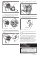
For tool with shallow driver bit hole A=12mm B=9mm Use only these type of driver bit. Follow the procedure 1. (Note) Bit-piece is not necessary. For tool with deep driver bit hole A=17mm B=14mm To install these types of driver bits, follow the procedure 1. A=12mm B=9mm To install these types of driver bits, follow the procedure 2. (Note) Bit-piece is necessary for installing the bit.
Proper fastening torque for standard bolt 2. N•m (kgf•cm) M16 140 (1428) 120 (1224) 100 (1020) 3. M14 2 80 (816) M16 M12 M14 60 (612) 40 (408) 20 (204) M10 M12 M8 0 M10 M8 1 1. Fastening time (second) 1 2 3 5. 2.
4. Make sure to place the lead wire in opposite side of the arm. 1 2 1 2 1. Rear cover 2. Screw 2. Raise the arm part of the spring and then place it in the recessed part of the housing with a slotted bit screwdriver of slender shaft or the like. 1 1. Lead wire 2. Carbon brush cap 5. Make sure that the carbon brush caps have fit into the holes in brush holders securely. 1 2 1. Recessed part 2. Spring 3 2 3. Arm 3. Use pliers to remove the carbon brush caps of the carbon brushes.
Center. • Driver bits • Hook • Plastic carrying case • Makita genuine battery and charger • Battery protector NOTE: Some items in the list may be included in the tool package as standard accessories. They may differ from country to country.
Makita Jan-Baptist Vinkstraat 2, 3070, Belgium Makita Corporation Anjo, Aichi, Japan www.makita.