
Operation Manual


8 ENGLISH
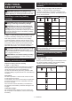
Impact force grade displayed
on panel
Maximum blows Application Work
Soft
1,800 min
-1
(/min) Tighteningwhenyouneedne
adjustmentwithsmalldiameter
bolt.
Assemblingfurnitures.
Reverse rotation auto stop
mode
3,500 min
-1
(/min) Loosening with auto stop
function.
Disassemblingbolts/nuts.
NOTE:Reverserotationautostopmodeisavailableonlywhenthetoolrotatescounterclockwise.Whenrotating
clockwise in reverse rotation auto stop mode, the impact force and speed are the same as Hard impact mode.
ASSEMBLY
CAUTION: Always be sure that the tool is
switched off and the battery cartridge is removed
before carrying out any work on the tool.
Selecting correct impact socket
Alwaysusethecorrectsizeimpactsocketforboltsand
nuts.Anincorrectsizeimpactsocketwillresultininac-
curateandinconsistentfasteningtorqueand/ordamage
to the bolt or nut.
Installing or removing impact socket
CAUTION: Make sure that the impact socket
and the mounting portion are not damaged before
installing the impact socket.
CAUTION: After inserting the impact socket,
make sure that it is rmly secured. If it comes out,
do not use it.
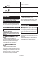
For impact socket without O-ring
and pin
►Fig.10: 1. Impact socket 2. Square drive
Aligntheholeinthesideoftheimpactsocketwiththe
detent pin on the square drive and push the impact
socketontothesquaredriveuntilitlocksintoplace.Tap
it lightly if required.
Toremovetheimpactsocket,simplypullitoff.
For impact socket with O-ring
and pin
►Fig.11: 1. Impact socket 2. O-ring 3.Pin
Move the O-ring out of the groove in the impact socket
and remove the pin from the impact socket. Fit the impact
socket onto the square drive so that the hole in the impact
socket is aligned with the hole in the square drive.
Insert the pin through the hole in the impact socket and
squaredrive.ThenreturntheO-ringtotheoriginalposi-
tion in the impact socket groove to retain the pin.
Toremovetheimpactsocket,followtheinstallation
procedures in reverse.
Installing hook
►Fig.12: 1. Groove 2. Hook 3. Screw
Thehookisconvenientfortemporarilyhangingthetool.
Thiscanbeinstalledoneithersideofthetool.Toinstall
the hook, insert it into a groove in the tool housing on
eithersideandthensecureitwithascrew.Toremove,
loosen the screw and then take it out.
OPERATION
CAUTION: Always insert the battery cartridge
all the way until it locks in place. If you can see the
red indicator on the upper side of the button, it is not
locked completely. Insert it fully until the red indicator
cannot be seen. If not, it may accidentally fall out of
thetool,causinginjurytoyouorsomeonearound
you.
►Fig.13
Holdthetoolrmlyandplacetheimpactsocketover
theboltornut.Turnthetoolonandfastenfortheproper
fastening time.
Theproperfasteningtorquemaydifferdependingupon
thekindorsizeofthebolt,thematerialoftheworkpiece
tobefastened,etc.Therelationbetweenfastening
torqueandfasteningtimeisshowninthegures.