
User Manual


8 ENGLISH
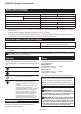
Indicating the remaining battery
capacity
Only for battery cartridges with the indicator
►Fig.3: 1. Indicator lamps 2. Check button
Pressthecheckbuttononthebatterycartridgetoindi-
catetheremainingbatterycapacity.Theindicatorlamps
light up for a few seconds.
Indicator lamps Remaining
capacity
Lighted Off Blinking
75% to 100%
50% to 75%
25% to 50%
0% to 25%
Charge the
battery.
Thebattery
mayhave
malfunctioned.
NOTE: Depending on the conditions of use and the
ambienttemperature,theindicationmaydifferslightly
fromtheactualcapacity.
Tool / battery protection system
Thetoolisequippedwithatool/batteryprotectionsys-
tem.Thissystemautomaticallycutsoffpowertothe
motortoextendtoolandbatterylife.Thetoolwillauto-
maticallystopduringoperationifthetoolorbatteryis
placed under one of the following conditions:
Overload protection
Whenthetoolorbatteryisoperatedinamannerthat
causesittodrawanabnormallyhighcurrent,thetool
automaticallystopswithoutanyindication.Inthissit-
uation, turn the tool off and stop the application that
caused the tool to become overloaded. Then turn the
tool on to restart.
Overheat protection
Whenthetoolorbatteryisoverheated,thetoolstops
automatically.Inthiscase,letthetoolandbatterycool
before turning the tool on again.
Overdischarge protection
Whenthebatterycapacityisnotenough,thetoolstops
automatically.Inthiscase,removethebatteryfromthe
toolandchargethebattery.
Switch action
CAUTION: Before installing the battery car-
tridge into the tool, always check to see that the
switch trigger actuates properly and returns to
the "OFF" position when released.
CAUTION: Switch can be locked in "ON" posi-
tion for ease of operator comfort during extended
use. Apply caution when locking tool in "ON"
position and maintain rm grasp on tool.
CAUTION: Do not install the battery cartridge
with the lock button engaged.
CAUTION: When not operating the tool,
depress the trigger-lock button from side to
lock the switch trigger in the OFF position.
►Fig.4: 1. Trigger-lock button
►Fig.5: 1. Switch trigger 2. Lock button 3. Trigger-
lock button
Topreventtheswitchtriggerfromaccidentallypulled,
the trigger-lock button is provided. To start the tool,
depress the trigger-lock button from A (
) side and pull
theswitchtrigger.Toolspeedisincreasedbyincreas-
ing pressure on the switch trigger. Release the switch
trigger to stop. After use, depress the trigger-lock button
from B ( ) side.
For continuous operation, depress the lock button while
pulling the switch trigger, and then release the switch
trigger.Tostopthetool,pulltheswitchtriggerfully,then
release it.
Speed change
NOTICE: Use the speed change knob only after
the tool comes to a complete stop. Changing the
toolspeedbeforethetoolstopsmaydamagethetool.
NOTICE: Always set the speed change knob
carefully into the correct position.Ifyouoperate
the tool with the speed change knob positioned half-
waybetweentheposition1andtheposition2,the
toolmaybedamaged.
NOTICE: If the rotation speed signicantly
decreases during operation in the high speed
mode, stop the tool and change the mode to the
low speed mode.Otherwise,themotormayget
overloadedandcauseamalfunctionorre.
Two speed ranges can be preselected with the speed
change knob.
To change the speed, turn the speed change knob so
that the pointer points to the position 1 for low speed or
the position 2 for high speed.
►Fig.6: 1. Pointer 2. Speed change knob
Accidental restart preventive
function
Ifyouinstallthebatterycartridgewhilepullingthe
switch trigger or locking the switch trigger, the tool does
not start. To start the tool, release the switch trigger, and
then pull the switch trigger.