
Technical data sheet


8 ENGLISH
Indicating the remaining battery
capacity
Only for battery cartridges with the indicator
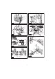
ŹFig.3: 1. Indicator lamps 2. Check button
3UHVVWKHFKHFNEXWWRQRQWKHEDWWHU\FDUWULGJHWRLQGL-
FDWHWKHUHPDLQLQJEDWWHU\FDSDFLW\7KHLQGLFDWRUODPSV
light up for a few seconds.
Indicator lamps Remaining
capacity
Lighted Off Blinking
75% to 100%
50% to 75%
25% to 50%
0% to 25%
Charge the
EDWWHU\
7KHEDWWHU\
PD\KDYH
malfunctioned.
NOTE: Depending on the conditions of use and the
DPELHQWWHPSHUDWXUHWKHLQGLFDWLRQPD\GLIIHUVOLJKWO\
IURPWKHDFWXDOFDSDFLW\
Tool / battery protection system
7KHWRROLVHTXLSSHGZLWKDWRROEDWWHU\SURWHFWLRQV\V-
WHP7KLVV\VWHPDXWRPDWLFDOO\FXWVRIISRZHUWRWKH
PRWRUWRH[WHQGWRRODQGEDWWHU\OLIH7KHWRROZLOODXWR-
PDWLFDOO\VWRSGXULQJRSHUDWLRQLIWKHWRRORUEDWWHU\LV
placed under one of the following conditions:
Overload protection
:KHQWKHWRRORUEDWWHU\LVRSHUDWHGLQDPDQQHUWKDW
FDXVHVLWWRGUDZDQDEQRUPDOO\KLJKFXUUHQWWKHWRRO
DXWRPDWLFDOO\VWRSVZLWKRXWDQ\LQGLFDWLRQ,QWKLVVLW-
uation, turn the tool off and stop the application that
caused the tool to become overloaded. Then turn the
tool on to restart.
Overheat protection
:KHQWKHWRRORUEDWWHU\LVRYHUKHDWHGWKHWRROVWRSV
DXWRPDWLFDOO\,QWKLVFDVHOHWWKHWRRODQGEDWWHU\FRRO
before turning the tool on again.
Overdischarge protection
:KHQWKHEDWWHU\FDSDFLW\LVQRWHQRXJKWKHWRROVWRSV
DXWRPDWLFDOO\,QWKLVFDVHUHPRYHWKHEDWWHU\IURPWKH
WRRODQGFKDUJHWKHEDWWHU\
Switch action
CAUTION: Before installing the battery car-
tridge into the tool, always check to see that the
switch trigger actuates properly and returns to
the "OFF" position when released.
CAUTION: Switch can be locked in "ON" posi-
tion for ease of operator comfort during extended
use. Apply caution when locking tool in "ON"
SRVLWLRQDQGPDLQWDLQ¿UPJUDVSRQWRRO
CAUTION: Do not install the battery cartridge
with the lock button engaged.
CAUTION: When not operating the tool,
depress the trigger-lock button from side to
lock the switch trigger in the OFF position.
ŹFig.4: 1. Trigger-lock button
ŹFig.5: 1. Switch trigger 2. Lock button 3. Trigger-
lock button
7RSUHYHQWWKHVZLWFKWULJJHUIURPDFFLGHQWDOO\SXOOHG
the trigger-lock button is provided. To start the tool,
depress the trigger-lock button from A (
) side and pull
WKHVZLWFKWULJJHU7RROVSHHGLVLQFUHDVHGE\LQFUHDV-
ing pressure on the switch trigger. Release the switch
trigger to stop. After use, depress the trigger-lock button
from B (
) side.
For continuous operation, depress the lock button while
pulling the switch trigger, and then release the switch
WULJJHU7RVWRSWKHWRROSXOOWKHVZLWFKWULJJHUIXOO\WKHQ
release it.
Speed change
NOTICE: Use the speed change knob only after
the tool comes to a complete stop. Changing the
WRROVSHHGEHIRUHWKHWRROVWRSVPD\GDPDJHWKHWRRO
NOTICE: Always set the speed change knob
carefully into the correct position.,I\RXRSHUDWH
the tool with the speed change knob positioned half-
ZD\EHWZHHQWKHSRVLWLRQDQGWKHSRVLWLRQWKH
WRROPD\EHGDPDJHG
NOTICE: ,IWKHURWDWLRQVSHHGVLJQL¿FDQWO\
decreases during operation in the high speed
mode, stop the tool and change the mode to the
low speed mode.2WKHUZLVHWKHPRWRUPD\JHW
RYHUORDGHGDQGFDXVHDPDOIXQFWLRQRU¿UH
Two speed ranges can be preselected with the speed
change knob.
To change the speed, turn the speed change knob so
that the pointer points to the position 1 for low speed or
the position 2 for high speed.
ŹFig.6: 1. Pointer 2. Speed change knob
Accidental restart preventive
function
,I\RXLQVWDOOWKHEDWWHU\FDUWULGJHZKLOHSXOOLQJWKH
switch trigger or locking the switch trigger, the tool does
not start. To start the tool, release the switch trigger, and
then pull the switch trigger.