EG2250A EG2850A EG4550A EG5550A EG6050A GB Petrol Generator Instructions for Use F Groupe Electrogène Manuel d'instructions D Generator Betriebsanleitung I Generatore a benzina Istruzioni per l’utilizzo NL Gebruiksaanwijzing Benzinegenerator E Generador a gasolina Manual de instrucciones
4 3 2 1 12 11 13 5 6 7 14 8 15 9 16 10 1 2 23 O 17 21 18 23 22 O I 22 I S 20 EG2250A EG2850A 19 3 EG4550A, EG5550A, EG6050A 4 7 28 27 8 29 5 6 16 5 7 2 29 28 8 24
22 13 12 30 31 9 23 10 11 12 11 25 26 11 12 48 10 32 49 46 33 3 47 2 34 13 14 35 33 37 36 10 15 38 39 34 39 16 3
0 41 42 21 17 18 35 43 19 44 20 45 8 21 22 23 24 4
25 26 27 5
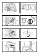
ENGLISH (Original instructions) Explanation of general view 1. 2. 3. 4. 5. 6. 7. 8. 9. 10. 11. 12. 13. 14. 15. CONTROL PANEL FUEL GAUGE FUEL TANK CAP ENGINE SWITCH CHOKE LEVER AIR CLEANER FUEL VALVE LEVER STARTER GRIP ENGINE SERIAL NUMBER OIL FILLER CAP/DIPSTICK AC CIRCUIT PROTECTORS AC CIRCUIT BREAKER DC CIRCUIT PROTECTOR DC OUTPUT TERMINAL 230V AC RECEPTACLE (Shape of socket varies by country) 16. GROUND TERMINAL 17. 18. 19. 20. 21. 22. 23. 24. 25. 26. 27. 28. 29. 30. 31. 32. 33.
GENERATOR SAFETY SYMBOLS and MEANINGS In accordance with the European requirements (eec Directives), the specified symbols as shown in the following table are used for the products and this instruction manual. Read the operator’s instruction manual. Fire, open light and smoking prohibited. Stay clear of the hot surface. Do not connect the generator to the commercial power lines. Exhaust gas is poisonous. Do not operate in an unventilated room. Gasoline Stop the engine before refueling.
• The load must be kept within the rating stated on generator rating plate. Overloading the generator will damage the unit or shorten its life. • The generator must not be run at excessive speeds. Operation at excessive speeds will increase the hazards of personal injury. • Do not modify parts which may increase or decrease the governed speed. • Only use extension cords that are grounded and are a sufficient wire gauge for the application.
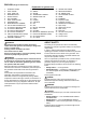
Oil Alert System (Fig. 14) The engine can be damaged if there is an insufficient amount of oil in the crankcase. The Oil Alert system prevents this from happening by automatically stopping the engine before the oil level in the crankcase falls below the safe limit (the engine switch will remain in the “I (ON)” position). When the oil alert system works, the oil level warning lamp lights up in red. The oil level should always be checked before each use, regardless of this Oil Alert system.
electrical load on the circuit, wait a few minutes and then reset the AC circuit breaker or AC circuit protector. DC Operation The DC terminals are used only for charging 12-volt automotive type batteries. Connecting the battery charging cables: 1. Before connecting the battery charging cables to a battery that is installed in a vehicle, disconnect the vehicle ground battery cable from the negative (-) terminal of the battery. WARNING: The battery gives off explosive gases.
Recommended Fuels This engine is certified to operate on regular unleaded gasoline with a pump octane rating of 86 or higher. Never use stale or contaminated gasoline or an oilgasoline mixture. Avoid getting dirt or water in the fuel tank. Regular unleaded gasoline containing no more than 10% ethanol (E10) or 5% methanol by volume can be used. In addition, the methanol must contain cosolvents and corrosion inhibitors.
WARNING: Failure to properly follow maintenance instructions and precautions can cause severe personal injury or loss of life. Always follow the procedures and precautions in the instruction manual. - Injury from moving parts. Do not run the engine unless instructed to do so. • Read the instructions before you operate the generator, and make sure you understand the instructions and have the tools and skills required. • To reduce the possibility of fire or explosion, be careful when working around gasoline.
NOTICE: Operating the engine without an air filter, with a damaged air filter, or with an improperly installed air filter will allow dirt to enter the engine, causing rapid engine wear. This type of damage is not covered by the Distributor’s Limited Warranty. 1. Remove the knob, unhook the two air cleaner cover clips, and then remove the air cleaner cover and the element. 2.
Fuel system damage or engine performance problems resulting from neglected storage preparation is not covered by the Distributor’s Limited Warranty. Fuel storage life can be extended by adding a gasoline stabilizer that is formulated for that purpose. Or, drain the LENGTH OF STORAGE Less than 1 month carburetor, sediment cup (if applicable) and/ or fuel tank to avoid fuel deterioration problems.
WARNING: Contact with a hot engine or exhaust system can result in serious burns or fire. Allow the engine cool before transporting or storing the generator. When transporting the generator, take care not to drop or strike the generator. Do not place heavy objects on the generator. When transporting the generator on a vehicle, secure to the generator frame as shown. TROUBLESHOOTING When the engine fails to start: Check if fuel is in the tank. ÅÆ If empty, refill the fuel tank. Check the fuel level.
WIRING DIAGRAM Electric Generator Panel Class 1 Mutual Inductor 9.6/12.5A Overcurrent Protective Device Class 2 Mutual Inductor Stud Main Coil Drive Coil 8A Overcurrent Protective Device Oil Level Flameout Rotor Coil Directcurrent Winding Engine Oil Spark Ignition Level Switch Plug Coil Note: Wiring is the same for the EG2250A and EG2850A.
Electric Generator Panel Class 1 Mutual Inductor 19.
SPECIFICATIONS MODEL EG2250A EG2850A EG4550A EG5550A EG6050A Type Brush, 2-poles, single phase Voltage regulating system AVR type AC Output Rated voltage-Frequency Generator 230 - 50 V-Hz Rated current A 8.7 11.3 17.4 21.7 24 Rated output VA (W) 2,000 2,600 4,000 5,000 5,500 Maximum output VA (W) 2,200 2,800 4,500 5,500 6,000 Rated power factor 1.0 Safety device type Circuit breaker DC Output Rated voltage V Rated current A 12 8.
- Carbon monoxide poisoning from engine exhaust. Operate outside away from open windows or doors. - Burns from hot parts. Let the engine and exhaust system cool before touching. - Injury from moving parts. Do not run the engine unless the instruction tells you to do so. Even then, keep your hands, fingers, and clothing away. When any protective guard or shield has been removed, do not run the engine. • To reduce the possibility of a fire or explosion, be careful when working around gasoline or batteries.
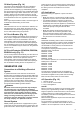
Handle Installation (Fig. 24) 1. Remove the two lugs in the pushrod inserted into the rack, and line up the hole on the pushrod with the hole on the rack. Next, insert the pushrod into the rack from the outside and then screw in the M8 flange bolt on the inside and tighten down the bolt. TORQUE: 17 - 22 lbf•ft (24 - 29 N•m, 2.4 - 3.0 kgf•m) Wheel Kit Installation (Fig. 25) 1.
FRANÇAIS (Instructions originales) Descriptif général 1. 2. 3. 4. 5. 6. 7. 8. 9. 10. 11. 12. 13. 14. 15. PANNEAU DE COMMANDE JAUGE À CARBURANT BOUCHON DU RÉSERVOIR À CARBURANT INTERRUPTEUR DU MOTEUR LEVIER DU STARTER FILTRE À AIR LEVIER DU ROBINET DE CARBURANT POIGNÉE DU DÉMARREUR NUMÉRO DE SÉRIE DU MOTEUR BOUCHON DE REMPLISSAGE D'HUILE/JAUGE DE NIVEAU PROTECTEURS DE CIRCUIT CA DISJONCTEUR CA PROTECTEUR DE CIRCUIT CC BORNE DE SORTIE CC PRISES CA 230 V (la forme des prises varie selon les pays) 16. 17. 18.
SÉCURITÉ DU GROUPE ÉLECTROGÈNE SYMBOLES et SIGNIFICATIONS En conformité avec les exigences européennes (Directives CEE), les symboles spécifiés comme indiqué dans le tableau suivant sont utilisés pour les produits et ce manuel d'instructions. Lire le manuel d'instructions de l'opérateur. Feu et flamme nue interdits et défense de fumer. Rester à l'écart des surfaces chaudes. Ne pas connecter le groupe électrogène aux lignes électriques commerciales. Le gaz d'échappement est toxique.
• Le silencieux devient très chaud pendant le fonctionnement et reste chaud pendant un certain temps après l'arrêt du moteur. Ne pas toucher le silencieux lorsqu'il est chaud. Attendre que le moteur refroidisse avant de ranger le groupe électrogène à l'intérieur. • L'essence est très inflammable et explosive dans certaines conditions. Ne pas fumer lors du ravitaillement du groupe électrogène ou à proximité de l'endroit où l'essence est stockée.
Tige du starter (Fig. 7) Disjoncteur CA (Fig. 10) Le starter permet de fournir un mélange de carburant enrichi lors du démarrage d'un moteur froid. Actionner la tige du starter manuellement pour ouvrir et fermer le starter. Tirer le starter vers « FERMÉ » pour enrichir le mélange pour le démarrage à froid. Le disjoncteur CA s'éteint automatiquement en cas de court-circuit ou de surcharge importante du groupe électrogène au niveau de la prise.
Applications CA Avant de connecter un appareil ou un cordon d'alimentation au groupe électrogène : • S'assurer qu'il est en bon état de fonctionnement. Les appareils ou les cordons d'alimentation défectueux peuvent provoquer un choc électrique. • Si un appareil se met à fonctionner de manière anormale, s'il devient lent ou s'arrête brusquement, le mettre hors tension immédiatement.
Fonctionnement à haute altitude À haute altitude, le mélange standard air-carburant du carburateur est trop riche, provoquant une baisse de la performance et une augmentation de la consommation de carburant. Un mélange très riche encrasse également la bougie d'allumage et rend le démarrage difficile. Le fonctionnement pendant des périodes prolongées à une altitude qui diffère de l'altitude à laquelle ce moteur a été certifié peut augmenter les émissions.
AVERTISSEMENT : Les gaz d'échappement provenant du groupe électrogène contiennent du monoxyde de carbone, un gaz toxique qui peut s'accumuler à des niveaux dangereux dans des endroits clos. L'inhalation de monoxyde de carbone peut provoquer des évanouissements ou la mort. Ne jamais faire fonctionner le groupe électrogène dans un endroit clos ou partiellement clos, où il peut y avoir des personnes.
Consignes de sécurité instructions et de disposer de l'outillage et des compétences nécessaires. • Pour diminuer les risques d'incendie ou d'explosion, être prudent lors de tout travail à proximité de l'essence. Pour le nettoyage des pièces, utiliser uniquement un solvant ininflammable et non de l'essence. Ne pas approcher de cigarettes, d'étincelles ou de flammes à proximité des pièces du système d'alimentation en carburant.
Changement de l'huile moteur (Fig. 15) Vidanger l'huile lorsque le moteur est encore chaud afin d'assurer une vidange rapide et complète. 1. Placer un récipient approprié sous le moteur pour recueillir l'huile. 2. Vidanger l'huile en retirant le bouchon de vidange d'huile, la rondelle d'étanchéité et le bouchon de remplissage d'huile/jauge de niveau. 3. Remettre le bouchon de vidange d'huile et une nouvelle rondelle d'étanchéité, puis serrer fermement le bouchon. 4.
3. Installer le pare-étincelles dans l'ordre inverse de la dépose. ENTREPOSAGE Préparation à l'entreposage Une préparation à l'entreposage appropriée est essentielle pour maintenir le groupe électrogène en bon état de fonctionnement et lui conserver son bel aspect. Les étapes suivantes contribueront à empêcher que la rouille et la corrosion n'affectent le fonctionnement et l'aspect du groupe électrogène et à faciliter le démarrage du moteur lors de la remise en service du groupe électrogène.
Huile moteur (Fig. 22) 1. Changer l'huile moteur. 2. Retirer la bougie d'allumage. 3. Verser une cuillère à café (5 - 10 cm3) d'huile moteur propre dans le cylindre. 4. Tirer plusieurs fois sur la poignée du démarreur pour distribuer l'huile dans le cylindre. 5. Reposer la bougie d'allumage. 6. Tirer doucement sur la poignée du démarreur jusqu'à ressentir une résistance. Le piston se déplace vers le haut de sa course de compression, à ce stade, et les soupapes d'admission et d'échappement sont fermées.
INFORMATIONS TECHNIQUES Informations sur les systèmes antipollution Source des émissions polluantes Le monoxyde de carbone, les oxydes d'azote et les hydrocarbures sont produits lors du processus de combustion. Il est très important de contrôler les émissions d'hydrocarbures et d'oxydes d'azote car, dans certaines conditions, ils réagissent à la lumière du soleil pour former un brouillard photochimique oxydant. Bien que le monoxyde de carbone ne réagisse pas de la même manière, il est toxique.
SCHÉMA DE CÂBLAGE Electric Generator Panel Class 1 Mutual Inductor 9.6/12.5A Overcurrent Protective Device Class 2 Mutual Inductor Stud Main Coil Drive Coil 8A Overcurrent Protective Device Oil Level Flameout Rotor Coil Directcurrent Winding Engine Oil Spark Ignition Level Switch Plug Coil Engine Remarque : Le câblage est le même pour EG2250A et EG2850A.
Electric Generator Panel Class 1 Mutual Inductor 19.5/24/26A Overcurrent Protective Device Class 2 Mutual Inductor 16A Overcurrent Protective Device 16A Overcurrent Protective Device Main Coil Drive Coil 8A Overcurrent Protective Device Oil Level Flameout Rotor Coil Fuel Cut Directcurrent Winding Charging Coil Startup Carburetor Engine Oil Spark Oil Cut-off Valve Level Switch Plug Ignition Coil Remarque : Le câblage est le même pour EG4550A, EG5550A et EG6050A.
SPÉCIFICATIONS MODÈLE EG2250A EG2850A EG4550A EG5550A EG6050A Type Balais, bipolaire, monophasé Système de régulation de tension Type AVR Sortie CA Groupe électrogène Tension nominale-Fréquence V-Hz Courant nominal A 230 - 50 8,7 11,3 17,4 21,7 24 Puissance de sortie nominale VA (W) 2000 2600 4000 5000 5500 Puissance de sortie maximale 2200 2800 4500 5500 6000 VA (W) Facteur de puissance nominale 1,0 Type de dispositif de sécurité Disjoncteur Sortie CC Tension nominale V
MONTAGE L'importance d'un montage correct Déballage Il est essentiel que le montage soit correctement effectué pour la sécurité de l'opérateur et la fiabilité de la machine. Toute erreur ou négligence commise par la personne qui effectue le montage ou une réparation de l'appareil peut facilement provoquer un mauvais fonctionnement, des dommages à l'appareil ou des blessures à l'opérateur. 1. Sortir le groupe électrogène et la boîte de pièces détachées du carton. 2.
Pièces détachées (kit de roues et poignées) et béquilles avant (uniquement pour les modèles EG4550A, EG5550A et EG6050A) Vérifier que toutes les pièces détachées correspondent à la liste suivante. Contacter le revendeur si l'une des pièces détachées ci-dessous n'est pas incluse avec le groupe électrogène.
Bac de batterie (Fig. 27) REMARQUE : La batterie n'est pas incluse. Utiliser une batterie (caractéristiques : 12 V-10 Ah, L x l x h : maximum 160 mm x 90 mm x 160 mm) disponible dans le commerce. 1. Connecter la ligne d'alimentation noire (électrode de masse) sur le groupe électrogène électrique à l'électrode négative de la batterie et la ligne d'alimentation rouge à l'électrode positive de la batterie. 2. Placer la batterie connectée aux lignes d'alimentation dans le bac de batterie sur la crémaillère. 3.
DEUTSCH (Originalanleitung) Übersicht 1. 2. 3. 4. 5. 6. 7. 8. 9. 10. 11. 12. 13. 14. 15. BEDIENFELD KRAFTSTOFFANZEIGE KRAFTSTOFFTANKDECKEL MOTORSCHALTER DROSSELHEBEL LUFTFILTER KRAFTSTOFFVENTILHEBEL ANLASSERGRIFF MOTORSERIENNUMMER ÖLFÜLLDECKEL/PEILSTAB WECHSELSTROMLEITUNGSSCHUTZSCHALTER WECHSELSTROMLEITUNGSTRENNSCHALTER GLEICHSTROMLEITUNGSSCHUTZSCHALTER GLEICHSTROMAUSGANG 230-VWECHSELSTROMSTECKDOSE (Dosenform variiert je nach Land) 16. 17. 18. 19. 20. 21. 22. 23. 24. 25. 26. 27. 28. 29. 30. 31. 32. 33.
GENERATORSICHERHEIT SYMBOLE und BEDEUTUNGEN Gemäß europäischen Anforderungen (EG-Richtlinien) werden die vorgeschriebenen Symbole für die Produkte und in dieser Betriebsanleitung verwendet wie in der folgenden Tabelle dargestellt. Lesen Sie die Betriebsanleitung. Von heißer Oberfläche fernhalten. Schließen Sie den Generator nicht an gewerbliche Stromleitungen an. Giftige Abgase. Nicht in ungelüfteten Räumen betreiben. Benzin Motor vor dem Nachtanken ausschalten. Wartung anfordern.
• Der Schalldämpfer wird während des Betriebs sehr heiß und bleibt auch nach dem Ausschalten des Motors eine Weile heiß. Achten Sie darauf, den Schalldämpfer nicht zu berühren, während er heiß ist. Lassen Sie den Motor vor dem Lagern des Generators in Innenräumen abkühlen. • Benzin ist äußerst leicht entflammbar und unter bestimmten Bedingungen explosiv. Rauchen Sie beim Betanken des Generators oder in der Nähe von Benzinlagerorten nicht.
Kraftstoffventilhebel nach dem Ausschalten des Motors wieder in die Stellung „AUS“. Wechselstrom-Leitungstrennschalter (Abb. 10) Drosselhebel (Abb.
Erdungsschaltungszustand wie eine Haushaltssteckdose auf. Wechselstromanwendungen Vor dem Anschluss eines Geräts oder Stromkabels an den Generator: • Stellen Sie sicher, dass es sich in einem guten Zustand befindet. Fehlerhafte Geräte oder Stromkabel können Stromschläge verursachen. • Schalten Sie ein Gerät sofort aus, wenn es in abnormaler Weise zu arbeiten beginnt, langsam wird oder plötzlich stoppt.
6. Schließen Sie das Fahrzeugerdungskabel wieder am negativen (-) Pol der Batterie an. Betrieb in großen Höhen Das standardmäßige Luft-Kraftstoff-Gemisch des Vergasers wird in großen Höhen zu fett, wodurch sich ein Leistungsverlust sowie ein höherer Kraftstoffverbrauch ergibt. Des Weiteren führt ein sehr fettes Gemisch zum Verschmutzen der Zündkerze und erschwert das Anlassen des Motors.
WARNUNG: Das aus dem Generator austretende Abgas enthält giftiges Kohlenmonoxid, das sich in geschlossenen Bereichen in gefährlich hohen Konzentrationen ansammeln kann. Das Einatmen von Kohlenmonoxid kann zu Bewusstlosigkeit und zum Tod führen. Betreiben Sie den Generator niemals in einem geschlossenen oder teilweise geschlossenen Bereich, in dem Personen anwesend sein könnten.
WARNUNG: Die nicht ordnungsgemäße Befolgung der Wartungsanleitungen und Vorsichtsmaßnahmen kann in schweren oder tödlichen Verletzungen resultieren. Befolgen Sie stets die Verfahren und Vorsichtsmaßnahmen in der Anleitung. Lassen Sie den Motor nur laufen, wenn Sie dazu angewiesen werden. • Lesen Sie die Anleitungen bevor Sie den Generator in Betrieb nehmen und stellen Sie sicher, dass Sie die Anleitungen verstanden haben und über die erforderlichen Werkzeuge und Fertigkeiten verfügen.
HINWEIS: Das nicht ordnungsgemäße Entsorgen von gebrauchtem Motoröl kann umweltgefährdend sein. Ermitteln sie vor dem Ölwechsel eine geeignete Entsorgungsmöglichkeit für das Altöl. Geben Sie Altöl nicht in eine Mülltonne und schütten Sie es nicht in einen Wasserabfluss oder auf den Boden. Ihre Gemeindeordnung und örtlichen Umweltvorschriften geben Ihnen detailliertere Anleitungen zur ordnungsgemäßen Entsorgung. Luftfilterwartung (Abb. 16 und Abb.
LAGERUNG Lagervorbereitung Eine ordnungsgemäße Vorbereitung auf die Lagerung trägt entscheidend zur Beibehaltung der Betriebsbereitschaft und guten optischen Erscheinung des Generators bei. Die folgenden Schritte helfen, eine durch Rost und Korrosion verursachte Beeinträchtigung der Leistung und des Erscheinungsbilds des Generators zu verhindern, und erleichtern das Starten des Motors bei der nächsten Verwendung des Generators.
Motoröl (Abb. 22) 1. Wechseln Sie das Motoröl. 2. Entfernen Sie die Zündkerze. 3. Gießen Sie einen Teelöffel (5 - 10 cm³) sauberes Motoröl in den Zylinder. 4. Ziehen Sie mehrmals am Anlassergriff, um das Öl im Zylinder zu verteilen. 5. Bringen Sie die Zündkerze wieder an. 6. Ziehen Sie langsam am Anlassergriff bis ein Widerstand spürbar ist. Der Kolben bewegt sich dabei auf seine Arbeitshubstellung zu und sowohl das Einlass- als auch das Auslassventil ist geschlossen.
Wenn an den Wechselstromsteckdosen kein Strom erzeugt wird: Vergewissern Sie sich, dass sich der WechselstromLeitungstrennsch alter in der Stellung „I (EIN)“ befindet. Prüfen Sie ob das Elektrogerät bzw. die Ausrüstung defekt ist. ÅÆ Schalten Sie den WechselstromLeitungstrennschalter andernfalls ein. ÅÆ Bringen Sie den Generator zu einem autorisierten MakitaGeneratorhändler, wenn keine Defekte vorliegen. Bei Defekten: - Tauschen Sie das Elektrogerät bzw. die Ausrüstung aus.
SCHALTPLAN Electric Generator Panel Class 1 Mutual Inductor 9.6/12.5A Overcurrent Protective Device Class 2 Mutual Inductor Stud Main Coil Drive Coil 8A Overcurrent Protective Device Oil Level Flameout Rotor Coil Directcurrent Winding Engine Oil Spark Ignition Level Switch Plug Coil Engine Hinweis: EG2250A und EG2850A haben denselben Schaltplan.
Electric Generator Panel Class 1 Mutual Inductor 19.5/24/26A Overcurrent Protective Device Class 2 Mutual Inductor 16A Overcurrent Protective Device 16A Overcurrent Protective Device Main Coil Drive Coil 8A Overcurrent Protective Device Oil Level Flameout Rotor Coil Fuel Cut Directcurrent Winding Charging Coil Startup Carburetor Engine Oil Spark Oil Cut-off Valve Level Switch Plug Ignition Coil Hinweis: EG4550A, EG5550A und EG6050A haben denselben Schaltplan.
TECHNISCHE DATEN MODELL EG2250A EG2850A EG4550A EG5550A EG6050A Typ Bürste, 2-polig, einphasig Spannungsregelung AVR-Ausführung Wechselstromausgang Nennspannungsfrequenz Generator 230 - 50 V-Hz Nennstrom A 8,7 11,3 17,4 21,7 24 Nennleistung VA (W) 2.000 2.600 4.000 5.000 5.500 Maximalleistung VA (W) 2.200 2.800 4.500 5.500 6.
MONTAGE Die Wichtigkeit einer ordnungsgemäßen Montage Eine ordnungsgemäße Montage ist eine Grundvoraussetzung für die Betriebssicherheit und den zuverlässigen Betrieb des Geräts. Jeder Fehler oder jedes Versehen der Person, die ein Gerät montiert oder wartet, kann leicht in einem fehlerhaften Betrieb, einer Beschädigung des Geräts oder einer Verletzung des Bedienungspersonals resultieren.
Losteile (Radbausatz und Griff) und Frontstütze (nur für die Modelle EG4550A, EG5550A, EG6050A) Gleichen Sie alle Losteile mit der folgenden Liste ab. Wenden Sie sich an Ihren Händler, falls jegliche der unten abgebildeten Losteile dem Generator nicht beiliegen. Nr. Bezeichnung Menge 1 10-Zoll-Rad 2 2 Radachse 2 3 Transportgriffwelle 2 4 Schraube, M8 x 100 2 5 Transportgriff 2 6 Frontstütze 2 7 Gummifuß 2 8 M8-Flanschmutter 6 Handgriffmontage (Abb.
3. Drehen Sie den Kraftstoffventilhebel am Generator in die Stellung „AUS“. Batterieablage (Abb. 27) HINWEIS: Die Batterie ist nicht im Lieferumfang enthalten. Verwenden Sie eine handelsübliche Batterie (Nennwerte: 12 V - 10 Ah, L x B x H: maximal 160 mm x 90 mm x 160 mm). 1. Schließen Sie das schwarze Stromkabel (Erdungskontakt) am Stromgenerator am negativen Pol der Batterie an und das rote Stromkabel am positiven Pol der Batterie an. 2.
ITALIANO (Istruzioni originali) Visione generale 1. 2. 3. 4. 5. 6. 7. 8. 9. 10. 11. 12. 13. 14. 15. 16.
SICUREZZA DEL GENERATORE SIMBOLI E SIGNIFICATO In conformità con le Direttive Europee, i simboli specificati indicati nella tabella seguente sono utilizzati per i prodotti e per il presente manuale. Leggere il manuale delle istruzioni per l’uso. Sono vietati fuoco, fiamme libere e fumo. Stare lontano dalla superficie calda. Non collegare il generatore alle linee elettriche commerciali. Il gas di scarico è tossico. Non utilizzare in ambiente non ventilato.
• I vapori del carburante sono estremamente infiammabili e possono prendere fuoco dopo l’avviamento del motore. In caso di fuoriuscita di carburante, pulire e lasciare asciugare prima di avviare il generatore. Altre informazioni per la sicurezza: • Per qualsiasi operazione e manutenzione è necessario indossare i dispositivi di protezione individuale. • Il carico deve essere tenuto entro il valore nominale dichiarato sulla targhetta del generatore.
Terminale di terra (Fig. 8) Il terminale di terra del generatore è collegato al telaio del generatore, alle parti metalliche che non sono sotto tensione e ai terminali di terra di ogni presa. Prima di usare il terminale di terra, consultare un elettricista qualificato, un ispettore elettricista o un’agenzia locale che abbia giurisdizione in merito alle leggi o normative locali applicabili in base all’utilizzo previsto per il generatore.
Funzionamento limite alla massima potenza per un’ora. La potenza massima è la seguente: EG2250A: 2,2 kW EG2850A: 2,8 kW EG4550A: 4,5 kW EG5550A: 5,5 kW EG6050A: 6,0 kW Per il funzionamento in continuo, non superare la potenza nominale. La potenza nominale è la seguente: EG2250A: 2,0 kW EG2850A: 2,6 kW EG4550A: 4,0 kW EG5550A: 5,0 kW EG6050A: 5,5 kW Si devono considerare i requisiti di potenza totale (VA) di tutte le apparecchiature collegate al generatore.
CONTROLLI PRE-UTILIZZO Controllare l’olio motore (Fig. 13) Prima di ogni utilizzo, controllare il livello dell’olio con il motore spento e il generatore su una superficie stabile e in piano. Utilizzare olio per motori 4 tempi che rispetti i requisiti API Service Categoria SJ o successive (o equivalente). Controllare sempre l’etichetta API SERVICE sul contenitore dell’olio per assicurarsi che siano indicate le lettere SJ o successive (o equivalente). 1.
AVVISO: • Se il motorino di avviamento viene azionato per più di 5 secondi, il motore potrebbe subire danni. Se il motore non si avvia, rilasciare l’interruttore e attendere 10 secondi prima di azionare nuovamente il motorino di avviamento. • Se il numero di giri del motorino di avviamento diminuisce dopo un certo periodo di tempo, vuol dire che la batteria deve essere ricaricata. Quando il motore si avvia, far tornare l’interruttore del motore in posizione "I (ON)".
Programma di manutenzione INTERVALLO DI SERVIZIO REGOLARE *3 ELEMENTI DI MANUTENZIONE Eseguire a ogni scadenza mensile o ore di funzionamento indicate, con priorità alla condizione che si verifica prima. Olio motore Controllo del livello Ogni utilizzo Controllo Vaschetta di raccolta dei sedimenti Pulizia Candela di accensione Controlloregolazione Pulizia Ogni 3 mesi o 50 ore. Ogni 6 mesi o 100 ore. Ogni anno o 300 ore. c Sostituzione Filtro aria Primo mese o 20 ore.
alta temperatura di infiammabilità. Al termine, lasciare asciugare completamente l’elemento filtrante. 3. Immergere l’elemento filtrante in olio motore pulito e strizzarlo per eliminare l’olio in eccesso. Se viene lasciato troppo olio motore nell’elemento filtrante, il motore emetterà fumo allo scarico durante l’avviamento. 4. Rimontare l’elemento filtrante e il coperchio.
deterioramento della benzina. Una temperatura di stoccaggio molto alta accelera il deterioramento della benzina. Il deterioramento della benzina può verificarsi entro pochi mesi, o anche meno, se la benzina non era nuova al momento del rifornimento. I danni all’impianto di alimentazione del carburante o eventuali problemi di prestazioni del motore causati dall’aver trascurato la preparazione alla conservazione non sono coperti dalla garanzia limitata del distributore.
Rimozione dallo stoccaggio Controllare il generatore come descritto nel capitolo "CONTROLLI PRE-UTILIZZO" del presente manuale. Riempire il serbatoio del carburante con benzina nuova se il carburante era stato scaricato durante la preparazione per lo stoccaggio. Se la benzina per il rifornimento viene tenuta in un contenitore, assicurarsi che contenga solo benzina nuova. La benzina è soggetta a ossidazione e deterioramento nel tempo e il suo utilizzo causerà difficoltà di avviamento.
Parti di ricambio I sistemi di controllo delle emissioni presenti sul motore Makita sono stati progettati, realizzati e omologati per essere conformi alle normative sulle emissioni in vigore. Pertanto, si raccomanda di usare parti di ricambio originali ogni volta che si esegue la manutenzione. Dato che i ricambi originali sono costruiti con gli stessi standard delle parti originali, le loro prestazioni sono affidabili.
Electric Generator Panel Class 1 Mutual Inductor 19.
DATI TECNICI MODELLO EG2250A EG2850A EG4550A EG5550A EG6050A Tipo Spazzole, 2 poli, monofase Sistema di regolazione della tensione Tipo AVR Uscita CA 230 - 50 Tensione-frequenza nominale V-Hz Generatore Corrente nominale A 8,7 11,3 17,4 21,7 24 Uscita nominale VA (W) 2.000 2.600 4.000 5.000 5.500 Uscita massima VA (W) 2.200 2.800 4.500 5.500 6.
ASSEMBLAGGIO Importanza del corretto assemblaggio Disimballaggio Un corretto assemblaggio è fondamentale per la sicurezza dell’operatore e l’affidabilità della macchina. Qualsiasi errore o disattenzione causato da chi è preposto all’assemblaggio o alla manutenzione della macchina può comportare un cattivo funzionamento, danni alla macchina o lesioni all’operatore. 1. Estrarre dall’imballaggio il generatore e la scatola con le parti da montare. 2. Controllare le parti da montare con l’elenco seguente.
Parti da montare (kit ruota e maniglie) e supporto anteriore (solo per modelli EG4550A, EG5550A, EG6050A) Controllare le parti da montare con l’elenco seguente. Contattare il rivenditore se una delle parti da montare mostrate in basso non sono comprese con il generatore. N.
Vano batteria (Fig. 27) NOTA: La batteria non è inclusa. Usare una batteria (potenza: 12 V10 Ah, Dimensioni massime (L x P x A): 160 mm x 90 mm x 160 mm) disponibile in commercio. 1. Collegare il cavo elettrico nero (terra) del generatore al polo negativo della batteria e cavo elettrico rosso al polo positivo della batteria. 2. Mettere la batteria, con i cavi elettrici già collegati, nel vano batteria sul telaio. 3.
NEDERLANDS (Originele instructies) Uitleg bij het overzicht 1. 2. 3. 4. 5. 6. 7. 8. 9. 10. 11. 12. 13. 14. 15. 16. BEDIENINGSPANEEL BRANDSTOFMETER TANKDOP MOTORSCHAKELAAR CHOKEHENDEL LUCHTREINIGER BRANDSTOFKRAAN STARTGREEP SERIENUMMER VAN MOTOR DOP/PEILSTOK VAN OLIEVULOPENING WISSELSTROOMBEVEILIGINGEN WISSELSTROOMONDERBREKER GELIJKSTROOMBEVEILIGING GELIJKSTROOMUITGANG WISSELSTROOMCONTACT 230 V (vorm van bus verschilt per land) AARDAANSLUITING 17. 18. 19. 20. 21. 22. 23. 24. 25. 26. 27. 28. 29. 30.
ALGEMENE VEILIGHEID SYMBOLEN en BETEKENIS In overeenstemming met de Europese vereisten (EEG Richtlijnen) worden de symbolen in onderstaande tabel gebruikt voor de producten en in deze handleiding. Lees de handleiding. Vlam, open vuur en roken zijn verboden. Raak geen hete delen aan. Sluit de generator niet aan op het openbare net. Giftige uitlaatgassen. Niet gebruiken in een ongeventileerde ruimte. Benzine Motor stoppen voordat brandstof wordt bijgevuld. Onderhoud inroepen.
• Brandstofwalmen zijn uiterst brandbaar en kunnen ontploffen wanneer de motor wordt gestart. Als brandstof wordt gemorst, moet u die wegvegen en laten drogen voordat de generator wordt gestart. COMPONENTEN (fig. 1) Andere veiligheidsinformatie: • Voor alle gebruik en onderhoud is persoonlijke beschermingsuitrusting vereist. • De belasting moet binnen de waarde worden gehouden die is aangegeven op het vermogensplaatje op de generator.
Gelijkstroomaansluiting De gelijkstroomaansluiting wordt alleen gebruikt voor het opladen van 12 voltaccu's zoals gebruikt in auto's. De rode aansluiting is positief (+) en de zwarte aansluiting is negatief (-). Let op dat u de accu met de juiste polariteit op de gelijkstroomaansluiting van de generator aansluit (positieve accupool op rode aansluiting van generator, en negatieve accupool op zwarte aansluiting van generator). Gelijkstroombeveiliging (fig.
EG2850A: 2,8 kW EG4550A: 4,5 kW EG5550A: 5,5 kW EG6050A: 6,0 kW Bij continu bedrijf mag het nominale vermogen niet worden overschreden. Het nominale vermogen is als volgt: EG2250A: 2,0 kW EG2850A: 2,6 kW EG4550A: 4,0 kW EG5550A: 5,0 kW EG6050A: 5,5 kW Houd daarbij rekening met het totale vermogen (VA) van alle apparaten tezamen die op de generator zijn aangesloten. Informatie over de nominale waarden van apparaten en gereedschappen wordt gewoonlijk vermeld bij het modelnummer of serienummer.
CONTROLES VÓÓR BEDRIJF De motorolie controleren (fig. 13) Controleer vóór elk gebruik het oliepeil; daarbij moet de motor uit staan en de generator op een stabiel en vlak oppervlak staan. Gebruik olie voor viertaktmotoren die voldoet aan (of beter is dan) API-klasse SJ of hoger (of equivalent). Controleer altijd het API-etiket op de olieverpakking en vergewis u ervan dat de klasse SJ of hoger (of equivalent) wordt vermeld. 1. Verwijder de dop/peilstok van de olievulopening en veeg de peilstok schoon. 2.
OPMERKING: • De motor kan beschadigd worden als de startmotor langer dan 5 seconden wordt gebruikt. Als de motor niet wil starten, laat u de schakelaar los en wacht u 10 seconden voordat u de startmotor opnieuw gebruikt. • Als de startmotor na een tijdje vertraagt, moet de accu worden opgeladen. Als de motor is gestart, laat u de motorschakelaar terugkeren naar de positie "I (AAN)". Als u de choke met de hand had gesloten, duwt u hem in de positie "OPEN" wanneer de motor opwarmt.
Onderhoudsschema REGELMATIG ONDERHOUD *3 ONDERHOUDSPUNTEN Voer deze uit na de aangegeven tijd of bedrijfsuren, naargelang welke eerst komt.
4. Plaats het luchtreinigerelement en de afdekking terug op hun plaats. Onderhoud van de vonkenvanger (verschillend per land) (fig. 20) De brandstofsedimentbeker reinigen De knaldemper is erg heet wanneer de generator werkt of gewerkt heeft. Laat hem afkoelen voordat u de vonkenvanger reinigt. De vonkenvanger moet elke 100 uur nagekeken worden om te zorgen dat hij blijft functioneren zoals bedoeld. Reinig de vonkenvanger als volgt: 1.
U kunt de opslagduur van benzine verlengen door een geschikte benzinestabilisator toe te voegen. Of u kunt de carburator, de sedimentbeker (indien van toepassing) en/ OPSLAGDUUR of de brandstoftank aftappen om kwaliteitsverlies van de brandstof te voorkomen. Voer onderhoud uit volgens onderstaande tabel: AANBEVOLEN ONDERHOUDSPROCEDURES OM HANDMATIG STARTEN TE VOORKOMEN Minder dan 1 maand Geen voorbereiding vereist. 1 tot 2 maanden Vul met verse benzine en voeg benzinestabilisator* toe.
TRANSPORT (fig. 23) TECHNISCHE INFORMATIE Als u de generator wilt transporteren, moet u eerst de motorschakelaar en de brandstofkraan uitzetten. Houd de generator stabiel en vlak om morsen van de brandstof te vermijden. Brandstofdampen en gemorste brandstof kunnen ontbranden. Het emissieregelsysteem WAARSCHUWING: Als u de motor of het uitlaatsysteem aanraakt wanneer ze heet zijn, kunt u ernstige brandwonden oplopen of brand veroorzaken.
Onderhoud Volg het onderhoudsschema. Onthoud dat dit schema is gebaseerd op de veronderstelling dat de machine wordt gebruikt voor het beoogde doel. Als de machine langdurig onder hoge belasting of bij hoge temperatuur wordt gebruikt, of in buitengewoon vochtige of stoffige omstandigheden, moet hij vaker nagekeken en onderhouden worden. BEDRADINGSSCHEMA Electric Generator Panel Class 1 Mutual Inductor 9.6/12.
Electric Generator Panel Class 1 Mutual Inductor 19.5/24/26A Overcurrent Protective Device Class 2 Mutual Inductor 16A Overcurrent Protective Device 16A Overcurrent Protective Device Main Coil Drive Coil 8A Overcurrent Protective Device Oil Level Flameout Rotor Coil Fuel Cut Directcurrent Winding Charging Coil Startup Carburetor Engine Oil Spark Oil Cut-off Valve Level Switch Plug Ignition Coil Opmerking: De bedrading van de EG4550A, EG5550A en EG6050A is gelijk.
SPECIFICATIES MODEL EG2250A EG2850A EG4550A EG5550A EG6050A Type Borstel, 2 polen, enkele fase Spanningsregeling AVR-type Wisselstroomuitgang Nominale spanning Frequentie Generator 230 - 50 V-Hz Nominale stroomsterkte A 8,7 11,3 17,4 21,7 24 Nominaal uitgangsvermogen VA (W) 2.000 2.600 4.000 5.000 5.500 Maximaal uitgangsvermogen VA (W) 2.200 2.800 4.500 5.500 6.
veiligheidsuitrusting. Let tijdens de montage in het bijzonder op de volgende punten: - Voordat u het werk begint, moet u de instructies lezen en controleren of u over alle vereiste kennis en gereedschap beschikt om het werk veilig te kunnen uitvoeren. • Vergewis u ervan dat de motor is uitgeschakeld voordat u enig onderhoud of reparatie begint. Zo sluit u enkele risico's uit: - Koolmonoxidevergiftiging door uitlaatgassen. Gebruik het apparaat buiten en uit de buurt van vensters en deuren.
Losse onderdelen (wielenkit en greep) en voorsteun (alleen voor model EG4550A, EG5550A, EG6050A) Controleer aan de hand van de volgende lijst of alle losse onderdelen aanwezig zijn. Neem contact op met uw dealer als een van de losse onderdelen niet is inbegrepen bij de generator. Nr. Naam Aantal 1 10 inchwiel 2 2 Wielas 2 3 As van transporthendel 2 4 Bout M8 x 100 2 5 Transporthendel 2 6 Standaard voor voorzijde 2 7 Rubberen voetje 2 8 Flensmoer M8 6 De greep installeren (fig.
Accubak (fig. 27) OPMERKING: De accu is niet inbegrepen. Gebruik een in de handel verkrijgbare accu (nominale waarde: 12 V-10 Ah, L x B x H: maximaal 160 mm x 90 mm x 160 mm). 1. Sluit de zwarte kabel (aardelektrode) van de generator aan op de negatieve accupool, en de rode kabel op de positieve accupool. 2. Nadat de accu is aangesloten, zet u hem in het batterijvak in het rek. 3. Zet de accu met de rubberen riem vast door de twee gespen ervan te bevestigen aan de haken van het accuvak.
ESPAÑOL (Instrucciones originales) Explicación de la vista general 1. 2. 3. 4. 5. 6. 7. 8. 9. 10. 11. 12. 13. PANEL DE CONTROL INDICADOR DE COMBUSTIBLE TAPÓN DEL DEPÓSITO DE COMBUSTIBLE INTERRUPTOR DEL MOTOR PALANCA DEL ESTRANGULADOR DEPURADOR DE AIRE PALANCA DE LA VÁLVULA DE COMBUSTIBLE EMPUÑADURA DEL ARRANCADOR NÚMERO DE SERIE DEL MOTOR TAPÓN DE LLENADO DE ACEITE / VARILLA INDICADORA DE NIVEL PROTECTORES DE CIRCUITO DE CA DISYUNTOR DE CIRCUITO DE CA PROTECTOR DE CIRCUITO DE CC 14.
• Títulos de seguridad — tales como INFORMACIÓN IMPORTANTE DE SEGURIDAD. • Sección de seguridad — tales como SEGURIDAD DEL GENERADOR. • Instrucciones — cómo utilizar este generador de forma correcta y segura. A lo largo de este manual se suministra información importante de seguridad. Léalo detenidamente.
- Mantenga alejados del generador los materiales inflamables. • El silenciador se calienta mucho durante el funcionamiento y permanece caliente durante un cierto tiempo tras haber detenido el motor. Tenga cuidado de no tocar el silenciador mientras esté caliente. Si el generador se almacena en interiores, deje que se enfríe el motor antes de almacenarlo. • La gasolina es altamente inflamable y es explosiva bajo ciertas condiciones.
combustible a la posición “O (APAGADO)” una vez detenido el motor. Barra del estrangulador (Fig. 7) El estrangulador se utiliza para proporcionar una mezcla de combustible enriquecida al arrancar el motor en frío. Opere la barra del estrangulador manualmente para abrir y cerrar el estrangulador. Tire de la barra hacia afuera hacia “CLOSED” (cerrado) para enriquecer la mezcla para el arranque en frío. Terminal de tierra (Fig.
• Si un aparato comienza a funcionar de un modo fuera de lo normal, se vuelve más lento o se detiene de repente, apáguelo inmediatamente. Desconecte el aparato y determine si hay un problema con el propio aparato o si se ha excedido la capacidad nominal de carga del generador. • Asegúrese de que el régimen eléctrico de la herramienta o del aparato no excede el régimen del generador. No exceda jamás el régimen de potencia máximo del generador.
Los caballos de fuerza del motor pueden descender alrededor del 3,5% por cada 300 metros (1000 pies) de incremento de la altitud, incluso con la modificación del carburador. Si no se realiza una modificación del carburador, el efecto de la altitud en caballos de fuerza será incluso más grande. Se puede mejorar el rendimiento a altitudes elevadas efectuando unas modificaciones específicas en el carburador.
Para evitar riesgos de incendio, mantenga el generador al menos a 1 metro (3 pies) de distancia de edificios y otras estructuras durante el funcionamiento. Mantenga alejados del motor los objetos inflamables. NOTA: No ponga en funcionamiento este generador a menos de 1 metro (3 pies) de distancia de edificios u otros obstáculos. Si lo hace, se puede provocar un sobrecalentamiento y/o daños en el generador.
Operar en exteriores lejos de ventanas y puertas abiertas. - Quemaduras producidas por piezas calientes. Deje que el motor y el sistema de gases de escape se enfríe antes de tocarlos. - Lesiones por piezas móviles. No ponga en marcha el motor a no ser que reciba instrucciones de hacerlo. • Lea las instrucciones antes de poner el generador en funcionamiento y asegúrese de que entiende las instrucciones y tiene las herramientas y las capacidades necesarias.
Cambio de aceite del motor (Fig. 15) Vacíe el aceite mientras el motor esté caliente para asegurar un vaciado rápido y completo. 1. Coloque un contenedor adecuado debajo del motor para recoger el aceite. 2. Evacue el aceite retirando el tapón de drenaje de aceite, la arandela de guarnición y el tapón de llenado de aceite / la varilla indicadora de nivel. 3. Vuelva a montar el tapón de drenaje de aceite y una nueva arandela de guarnición y apriete el tapón firmemente. 4.
2. Utilice un cepillo para eliminar los sedimentos de carbón de la rejilla del parachispas. El parachispas deberá estar libre de roturas o grietas. Inspecciónelo y sustitúyalo si estuviera dañado. 3. Instale el parachispas en el orden inverso al desmontaje. ALMACENAJE Preparación para el almacenaje La preparación debida de almacenaje es esencial para conservar el generador sin que presente problemas y con buen aspecto.
4. Deje que salga toda la gasolina y vuelva a instalar la taza de sedimentos. Aceite del motor (Fig. 22) 1. Cambie el aceite del motor. 2. Retire la bujía. 3. Ponga una cucharadita (5 - 10 cc) de aceite limpio para motores en el cilindro. 4. Tire varias veces de la empuñadura del arrancador para distribuir el aceite en el cilindro. 5. Vuelva a montar la bujía. 6. Tire lentamente de la empuñadura del arrancador hasta notar resistencia.
INFORMACIÓN TÉCNICA Información del sistema de control de las emisiones de escape Origen de las emisiones de escape El proceso de combustión produce monóxido de carbono, óxidos de nitrógeno, e hidrocarburos. El control de los hidrocarburos y de los óxidos de nitrógeno es muy importante porque, bajo ciertas condiciones, reaccionan para formar humo fotoquímico cuando se exponen a la luz solar. El monóxido de carbono no reacciona del mismo modo, pero es tóxico.
DIAGRAMA DE CONEXIONES Electric Generator Panel Class 1 Mutual Inductor 9.6/12.5A Overcurrent Protective Device Class 2 Mutual Inductor Stud Main Coil Drive Coil 8A Overcurrent Protective Device Oil Level Flameout Rotor Coil Directcurrent Winding Engine Oil Spark Ignition Level Switch Plug Coil Engine Nota: Las conexiones eléctricas son las mismas para EG2250A y EG2850A.
Electric Generator Panel Class 1 Mutual Inductor 19.
ESPECIFICACIONES MODELO EG2250A EG2850A EG4550A EG5550A EG6050A Tipo Con escobillas, 2 polos, monofásico Sistema de regulación de voltaje Tipo AVR Salida de CA Generador 230 - 50 Frecuencia de tensión nominal V-Hz Corriente nominal A 8,7 11,3 17,4 21,7 24 Salida nominal VA (W) 2000 2600 4000 5000 5500 Salida máxima VA (W) 2200 2800 4500 5500 6000 Factor de potencia nominal 1,0 Tipo de dispositivo de seguridad Disyuntor de circuito Salida de CC Tensión nominal V Corrient
MONTAJE La importancia de un montaje adecuado Desembalaje El montaje correcto es esencial para la seguridad del operador y la fiabilidad de la máquina. Cualquier error o despiste cometido por la persona que monta o mantiene una unidad puede resultar en un funcionamiento defectuoso, daños en la máquina o lesiones para el operador. 1. Retire el generador y la caja con las piezas sueltas del embalaje de cartón. 2. Compruebe las piezas sueltas frente a la lista de contenido siguiente.
Piezas sueltas (kit de ruedas y tiradores) y soporte frontal (solo para los modelos EG4550A, EG5550A y EG6050A) Compruebe todas las piezas sueltas frente a la lista siguiente. Póngase en contacto con su distribuidor si falta alguna de las piezas sueltas mostradas a continuación incluidas con el generador. N.
Bandeja de la batería (Fig. 27) NOTA: La batería no está incluida. Utilice una batería (potencia: 12 V - 10 Ah, Dimensiones máximas (L x Al x An): 160 mm x 90 mm x 160 mm) disponible en el mercado. 1. Conecte la línea de potencia negra (electrodo de masa) en el generador eléctrico al electrodo negativo en la batería y la línea de potencia roja al electrodo positivo en la batería. 2. Coloque la batería conectada a las líneas de potencia en la caja de batería del bastidor. 3.
Makita Corporation EG2250A-6L-0913 TRD 3-11-8, Sumiyoshi-cho, Anjo, Aichi 446-8502 Japan www.makita.