Original Instruction Manual Instructions d’emploi d’origine Originalbetriebsanleitung Manuale di istruzioni originale Originele gebruiksaanwijzing Instrucciones de manejo originales Instruções de serviço original Original brugsanvisning Πρωτότυπο εγχειρίδιο οδηγιών Orijinal Kullanım Kılavuzu Important: Read this instruction manual carefully before putting the Petrol Brushcutter into operation and strictly observe the safety regulations! Preserve instruction manual carefully! Important : Veuillez lire atten
English (Original instructions) Thank you very much for purchasing the MAKITA Outdoor Power Equipment. We are pleased to recommend to you the MAKITA product which is the result of a long development program and many years of knowledge and experience. Please read this booklet which refers in detail to the various points that will demonstrate its outstanding performance. This will assist you to obtain the best possible result from your MAKITA product. Table of Contents Page Symbols ......................
SAFETY INSTRUCTIONS General Instructions – Read this instruction manual to become familiar with handling of the equipment. Users insufficiently informed will risk danger to themselves as well as others due to improper handling. – It is recommended only to lend the equipment to people who have proven to be experienced. Always hand over the instruction manual. – First users should ask the dealer for basic instructions to familiarize oneself with the handling of brushcutters.
Start the brushcutter only in accordance with the instructions. – Do not use any other methods for starting the engine! – Use the brushcutter and the tools only for such applications as specified. – Only start the engine, after the entire assembly is done. Operation of the device is only permitted after all the appropriate accessories are attached! – Before starting make sure that the cutting tool has no contact with hard objects such as branches, stones etc. as the cutting tool will revolve when starting.
Method of operation – Only use in good light and visibility. During the winter season beware of slippery or wet areas, ice and snow (risk of slipping). Always ensure a safe footing. – Never cut above waist height. – Never stand on a ladder. – Never climb up into trees to perform cutting operation. – Never work on unstable surfaces. – Remove sand, stones, nails etc. found within the working range. Foreign particles may damage the cutting tool and can cause dangerous kick-backs.
Never straighten or weld damaged cutting tools. – Pay attention to the environment. Avoid unnecessary throttle operation for less pollution and noise emissions. Adjust the carburetor correctly. – Clean the equipment at regular intervals and check that all screws and nuts are well tightened. – Never service or store the equipment in the vicinity of naked flames. – Always store the equipment in locked rooms and with an emptied fuel tank.
TECHNICAL DATA EM4351UH, EM4350UH, EM4350LH Model Handle type Dimensions: length x width x height (without cutting tool) Mass (without plastic guard and cutting tool) mm EM4351UH EM4350UH EM4350LH Bike handle Bike handle Loop handle 1,812 x 618 x 528 1,812 x 635 x 460 1,812 x 339 x 250 8.6 8.3 7.9 kg Volume (fuel tank) L 0.6 Volume (oil tank) L 0.1 3 43.0 Engine displacement cm Maximum engine performance kW Engine speed at recommended max.
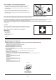
DESIGNATION OF PARTS EM4351UH EM4350UH EM4350LH 4 4 12 12 8 9 9 12 9 7 7 11 11 11 4 16 10 10 13 13 16 10 13 15 14 14 14 15 15 5 GB 6 3 19 18 17 1 20 2 8 DESIGNATION OF PARTS 1 Fuel tank 2 Recoil starter 3 Air cleaner 4 I-O and throttle lock switch (on/off) 5 Spark plug 6 Exhaust muffler 7 Clutch case 8 Rear grip 9 Hanger 10 Handle 11 Throttle lever 12 Control cable 13 Shaft 14 Protector (Cutting tool guard) 15 Gear Case/Head case 16 Handle hol
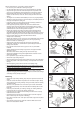
MOUNTING OF HANDLE CAUTION: Before doing any work on the equipment, always stop the engine and pull the spark plug connector off the spark plug. Always wear protective gloves! CAUTION: Start the engine only after having assembled it completely. For model EM4351UH, EM4350UH Insert the shaft of the handle into the grip as shown. Align the screw hole in the grip with the one in the shaft. Tighten the screw securely. Grip Screw Handle – Loosen knob (1).
MOUNTING OF PROTECTOR To meet the applicable safety provisions, only the tool/protector combinations as indicated in the table must be used. Be sure to use genuine MAKITA metal blades (including saw blade and cutter blade) or nylon cutting head. – The metal blade must be well polished, free of cracks or breakage. If the metal blade hits against a stone during operation, stop the engine and check the blade immediately.
– In use of the metal blade, fix the protector (3) to the clamp (2) with two bolts (1). (1) NOTE: Tighten the right and left bolts evenly so that the gap between the clamp (2) and the protector (3) will be constant. Otherwise, the protector sometimes may not function as specified. (2) (3) (1) (2) (3) – In cases where the nylon cord cutter is to be used, be sure to mount the nylon cord cutter protector (4) onto the metal blade protector (3).
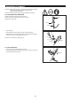
MOUNTING OF METAL BLADE OR NYLON CUTTING HEAD Be sure to use genuine MAKITA metal blades or nylon cutting head. – The metal blade must be well polished, free of cracks or breakage. If the metal blade hits against a stone during operation, stop the engine and check the blade immediately. – Polish or replace the metal blade every three hours of operation. Hex wrench – If the nylon cutting head hits against a stone during operation, stop the engine and check the nylon cutting head immediately.
BEFORE START OF OPERATION Inspection and refill of engine oil – Perform the following procedure, with the engine cooled down. – Assure that the engine is on a flat horizontal surface and confirm if the oil level is between the lower or upper limit of the oil indicator. – If the oil level is below the lower limit, remove the oil cap and add oil. – The area surrounding the external marks is transparent, so the amount of oil inside can be checked without having to remove the oil cap.
Note • Do not replace oil with the engine in a tilted position. • Filling with oil while engine is tilted leads to overfilling which causes oil contamination and/or white smoke. After refilling oil – Wipe with a rag any spilled oil immediately. REFUELING Handling of fuel It is necessary to handle fuel with utmost care. Fuel may contain substances similar to solvents. Refueling must be performed in a sufficiently ventilated room or in the open air. Never inhale fuel vapor, and keep fuel away from you.
CORRECT HANDLING OF MACHINE Attachment of shoulder harness – Adjust the strap length so that the metal blade will be kept parallel with the ground. Buckle For EM4351UH, EM4350UH Hold the harness on your back, attach it with the buckle, and adjust the length of the bands. NOTE: Be careful not to trap clothing, etc., in the buckle. EM4351UH EM4350UH For EM4350LH Band plate 1) Stand as the band plate closer to you. And let your arms and head pass through the band.
POINTS IN OPERATION AND HOW TO STOP Observe the applicable accident prevention regulations! Before starting the engine, always set the handle in the proper position. Otherwise the cutting tool may turn suddenly and cause injury, because the throttle cable may be pulled or bent, and open the throttle. STARTING Move at least 3 m away from the place of refueling. Place the unit on the ground taking care that the cutting tool does not come into contact with the ground or any other objects.
5) Recoil starter Make sure you have a firm footing. Hold the unit with your left hand and press it down firmly. CAUTION: Do not stand or kneel on the throttle cable. The internal wire may be pulled and the cutting tool may start rotating unintentionally. Do not open the throttle. Pull the starter knob gently until a certain resistance is felt. Then, return the starter knob, and pull it strongly. Never pull the rope to the full extension. Once the starter knob is pulled, never release your hand immediately.
STOPPING 1) Release the throttle lever (2) fully, and when the engine rpm has lowered, set the I-O switch (1) to STOP the engine will now stop. 2) The cutting tool continues to rotate a while after stopping the engine. Wait until it stops completely. (1) STOP (2) STOP (2) EM4350UH EM4351UH (1) EM4350LH ADJUSTMENT OF IDLE SPEED When it is necessary to adjust the idle speed, perform it by the carburetor adjusting screw. CHECKUP OF IDLE SPEED – Set the idle speed to 3,000 min-1.
RESHARPENING THE CUTTING TOOL CAUTION: The cutting tools shown in the illustration are not to be sharpened. Manual resharpening will result in imbalances of the cutting tool causing vibrations and damage to the equipment. NOTE: To increase the service life of the cutter blade it may be turned over once, until both cutting edges have become blunt. NYLON CUTTING HEAD The nylon cutting head is a dual line trimmer head that has bump & feed mechanism.
Mount the spool in the housing so that the grooves and protrusions on the spool match up with those in the housing. Keep the side with letters on the spool visible on the top. Now, unhook the ends of the cord from their temporary position and feed the cords through the eyelets to come out of the housing. Eyelets Align the protrusion on the underside of the cover with the slots of the eyelets. Then push cover firmly onto the housing to secure it. Make sure the latches fully spread in the cover.
4. Wind the lines up firmly to the direction slown by left-hand (LH) arrow on the flange. Do not cross the lines. To “LH” direction Wind tightly 5. Wind all but about 100 mm (3-15/16”) of the Cords, leaving the end temporarily hooked through a notch on the side of the spool. 100 mm from notches 6. Put tab knob onto the housing hub, positioning it can freely move up and down against spring tension. Put the spool into the housing, aligning the teeth on spool and tap knob alternately like gears.
SERVICING INSTRUCTIONS CAUTION: Before doing any work on the equipment, always stop the engine and pull the plug cap off the spark plug (see “checking the spark plug”). Always wear protective gloves! To ensure a long service life and to avoid any damage to the equipment, the following servicing operations should be performed at regular intervals. Daily checkup and maintenance – Before operation, check the machine for loose screws or missing parts.
5) Set the engine level, and gradually fill up to upper limit mark with new oil. 6) After filling, tightly secure oil cap, so that it will not loosen and cause leaks. If oil cap is not tightly secured, it may leak. POINTS ON OIL – Never discard replaced engine oil in garbage, earth or sewage ditch. Disposal of oil is regulated by law. In disposal, always follow the relevant laws and regulations. For any points remaining unknown, contact Authorized Service Agent.
CHECKING THE SPARK PLUG – Only use the supplied universal wrench to remove or to install the spark plug. – The gap between the two electrodes of the spark plug should be 0.7 - 0.8 mm (0.028” - 0.032”). If the gap is too wide or too narrow, adjust it. If the spark plug is clogged or contaminated, clean it thoroughly or replace it. Place the plug cap properly as illustrated after checking. CAUTION: Never touch the spark plug connector while the engine is running (danger of high voltage electric shock). 0.
REPLACEMENT OF FUEL PIPE CAUTION: INFLAMMABLES STRICTLY PROHIBITED Fuel pipe Interval of Cleaning and Inspection: Daily (every 10 operating hours) Replacement: Annually (every 200 operating hours) Replace the fuel pipe every year, regardless of operating frequency. Fuel leakage may lead to fire. If any leakage is detected during inspection, replace the fuel pipe immediately. INSPECTION OF BOLTS, NUTS AND SCREWS – Retighten loose bolts, nuts, etc. – Check the fuel cap and oil cap for tightness.
Operating time Before After operation refuleling Item Daily (10h) 30h 50h 200h Before storage Corresponding P 13 Inspect/clean Engine oil *1 Replace Tightening parts (bolt, nut) 22 Inspect 24 Clean/inspect — Fuel tank *3 Drain fuel 25 Throttle lever Check function — Stop switch Check function 22 Cutting tool Inspect 10 Idle speed Inspect/adjust 18 Air cleaner Clean 23 Spark plug Inspect 24 Cooling air passage and cylinder fins Clean/inspect 25 Inspect 25 Fuel pipe *2
TROUBLESHOOTING Before making a request for repairs, check for trouble by yourself. If any abnormality is found, control your machine according to the description of this manual. Never tamper or dismount any part contrary to the description. For repairs, contact Authorized Service Agent or local dealership. State of abnormality Probable cause (malfunction) I-O switch is set to STOP. Set the I-O switch to OPERATION.
Deutsch (Originalanweisungen) Vielen Dank, dass Sie sich für den Kauf eines motorgetriebenen Werkzeugs von MAKITA entschieden haben. Wir freuen uns, Ihnen die Motorsense von MAKITA anbieten zu können; unsere Produkte sind das Ergebnis eines langen Entwicklungsprogramms und vieler Jahre an Erkenntnissen und Erfahrungen. Lesen Sie diese Broschüre mit detaillierten Informationen zu den verschiedenen Punkten, die die herausragende Leistung dieses Produkts demonstrieren, aufmerksam durch.
SICHERHEITSVORSCHRIFTEN Allgemeine Sicherheitsregeln – Lesen Sie diese Betriebsanleitung durch und machen Sie sich mit dem Umgang mit diesem Werkzeug vertraut. Unzureichend informierte Bediener können durch unsachgemäßen Umgang mit dem Werkzeug sich und andere gefährden. – Verleihen Sie das Werkzeug nur an Personen, die nachweislich über Erfahrungen im Umgang mit derartigen Werkzeugen verfügen. Überreichen Sie stets auch diese Betriebsanleitung.
Starten Sie die Motorsense nur gemäß den Anleitungen. – Starten Sie den Motor auf keine andere Weise! – Verwenden Sie die Motorsense und die Werkzeuge nur für die angegebenen Zwecke. – Starten Sie den Motor nur, wenn das Werkzeug vollständig zusammengebaut ist. Der Betrieb des Werkzeugs ist nur gestattet, wenn alles dazugehörige Zubehör anmontiert ist! – Überprüfen Sie vor dem Starten, dass das Schneidwerkzeug keine harten Gegenstände (Geäst, Steine usw.
Handhabung – Verwenden Sie das Werkzeug nur bei guten Licht- und Sichtverhältnissen. Achten Sie im Winter auf rutschige oder nasse Bereiche, z. B. auf vereiste oder schneebedeckte Flächen (Rutschgefahr). Sorgen Sie immer für einen sicheren Stand. – Schneiden Sie niemals über Hüfthöhe. – Schneiden Sie niemals auf einer Leiter stehend. – Klettern Sie niemals auf Bäume, um mit dem Werkzeug zu schneiden. – Arbeiten Sie niemals auf nicht stabilen Flächen. – Entfernen Sie Sand, Steine, Nägel usw.
Beschädigte Schneidwerkzeuge dürfen auf keinen Fall begradigt oder geschweißt werden. – Nehmen Sie Rücksicht auf die Umwelt und auf Ihre Nachbarn. Vermeiden Sie ein unnötiges Betätigen des Gashebels, damit Umweltbelastung und Geräuschentwicklung so gering wie möglich gehalten werden. Achten Sie auf eine korrekte Vergasereinstellung. – Reinigen Sie das Werkzeug regelmäßig und überprüfen Sie, ob alle Schrauben und Muttern fest angezogen sind.
TECHNISCHE DATEN EM4351UH, EM4350UH, EM4350LH Modell EM4351UH EM4350UH EM4350LH Fahrradgriff Fahrradgriff Bügelgriff 1.812 x 618 x 528 1.812 x 635 x 460 1.812 x 339 x 250 8,6 8,3 7,9 Typ des Griffs Abmessungen: Länge x Breite x Höhe (ohne Schneidwerkzeug) mm Gewicht (ohne Kunststoffschutz und Schneidwerkzeug) kg Volumen (Kraftstofftank) L 0,6 Volumen (Öltank) L 0,1 3 43,0 Motor-Hubraum cm Maximale Motorleistung kW Motordrehzahl bei empfohlener max. Wellendrehzahl 1,5 bei 7.
BEZEICHNUNG DER BAUTEILE EM4351UH EM4350UH EM4350LH 4 4 12 12 8 9 9 12 9 7 11 11 11 7 4 16 10 10 13 13 16 10 13 15 14 14 15 14 15 5 D 6 3 19 18 17 1 20 2 60 BEZEICHNUNG DER BAUTEILE 1 Kraftstofftank 2 Seilzugstarter 3 Luftfilter 4 EIN/AUS-Schalter und Schalter für Gashebelentriegelung 5 Zündkerze 6 Auspuffschalldämpfer 7 Kupplungsgehäuse 8 Hinterer Griff 9 Einhänger 10 Griff 11 Gashebel 12 Bowdenzug und Steuerkabel 13 Welle 14 Schutz (Schutz für
MONTIEREN DES GRIFFS ACHTUNG: Stoppen Sie vor allen Arbeiten am Werkzeug den Motor und ziehen Sie den Zündkerzenstecker von der Zündkerze. Tragen Sie immer Schutzhandschuhe! ACHTUNG: Stellen Sie vor dem Starten sicher, dass das Werkzeug wieder vollständig zusammengebaut ist. Für die Modelle EM4351UH, EM4350UH Setzen Sie den Stiel des Tragegriffs in den Handgriff ein, wie in der Abbildung dargestellt. Richten Sie die Schraubenbohrung im Handgriff mit der Bohrung im Stiel aus.
MONTIEREN DES SCHUTZES Aufgrund der geltenden Sicherheitsvorschriften dürfen nur die in dieser Übersicht aufgezeigten Werkzeug/Schutz-Kombinationen verwendet werden. Verwenden Sie ausschließlich Original-Metallblätter bzw. einen Original-Nylon-Schneidkopf von MAKITA (gilt sowohl für Sägeblätter als auch für Schneidblätter). – Das Metallblatt muss gut geschliffen sein und darf keine Risse oder Brüche aufweisen.
– Befestigen Sie bei Verwendung eines Metallblatts den Schutz (3) mit Hilfe von zwei Schrauben (1) an der Klemme (2). HINWEIS: Ziehen Sie die rechte und linke Schraube gleichmäßig fest, sodass die Lücke zwischen der Klemme (2) und dem Schutz (3) gleich bleibt. Andernfalls könnte der Schutz ggf. nicht wie angegeben funktionieren.
MONTIEREN DES METALLBLATTS / NYLON-SCHNEIDKOPFS Verwenden Sie ausschließlich originale Metallblätter / Nylon-Schneidköpfe von MAKITA. – Das Metallblatt muss gut geschliffen sein und darf keine Risse oder Brüche aufweisen. Falls das Metallblatt während des Betriebs gegen Steine schlägt, stoppen Sie den Motor und überprüfen Sie das Metallblatt sofort. – Schleifen oder ersetzen Sie das Metallblatt nach jeweils drei Betriebsstunden.
VOR DEM BETRIEB Inspektion und Nachfüllen von Motoröl – Gehen Sie dazu, bei abgekühltem Motor, wie folgt vor. – Legen Sie das Werkzeug unbedingt auf einer ebenen Fläche ab und überprüfen Sie, ob der Ölstand zwischen der Untergrenze und der Obergrenze an der Ölstandsanzeige liegt. – Wenn der Ölstand unter der Untergrenze liegt, nehmen Sie den Öldeckel ab, und füllen sie Öl auf.
Hinweis • Wechseln Sie das Öl nicht in geneigter Position des Motors. • Beim Auffüllen von Öl mit dem Motor in einer geneigten Position wird zu viel Öl aufgefüllt, und es kann zu Ölverschmutzungen und/oder Ölnebelbildung kommen. Nach dem Auffüllen von Öl – Wischen Sie danebengelaufenes Öl sofort mit einem Putzlappen ab. AUFTANKEN Umgang mit Kraftstoff Beim Umgang mit Kraftstoff ist äußerste Vorsicht geboten. Kraftstoffe können Lösungsmitteln ähnliche Substanzen enthalten.
RICHTIGE HANDHABUNG DES WERKZEUGS Befestigen des Schultergurts – Stellen Sie die Gurtlänge so ein, dass das Metallblatt parallel zum Boden geführt wird. Gurtschloss Für EM4351UH, EM4350UH Halten Sie den Gurt auf Ihrem Rücken, befestigen Sie den Gurt im Gurtschloss, und stellen Sie die Länge der Bänder ein. HINWEIS: Achten Sie darauf, dass sich Ihre Kleidung usw. nicht im Gurtschloss verfängt. EM4351UH EM4350UH Für EM4350LH Gurtplatte 1) Legen Sie die Gurtplatte an.
WICHTIGE BETRIEBSSCHRITTE UND STOPPEN DES WERKZEUGS Beachten Sie die geltenden Bestimmungen zur Unfallverhütung! Bringen Sie immer erst den Griff in die ordnungsgemäße Stellung, bevor Sie das Werkzeug starten. Andernfalls kann es aufgrund von Zug oder Biegung des Gasbowdenzugs zu einem Gasgeben und dadurch zu einem unerwarteten Rotieren des Werkzeugs kommen. STARTEN Bewegen Sie sich mindestens 3 m von dem Platz des Auftankens weg.
5) Seilzugstarter Achten Sie auf sicheren und festen Stand. Halten Sie das Werkzeug mit der linken Hand und drücken Sie es fest nach unten. ACHTUNG: Stellen oder knien Sie sich niemals auf den Gas-Bowdenzug. Anderenfalls könnte das Seil im Inneren gezogen werden, wodurch sich das Schneidwerkzeug unbeabsichtigt zu drehen beginnt. Geben Sie kein Gas. Ziehen Sie leicht am Startergriff, bis Sie einen gewissen Widerstand spüren.
STOPPEN 1) Lassen Sie den Gashebel (2) vollkommen los, und bringen Sie, nachdem sich die Motordrehzahl verlangsamt hat, den EIN/AUSSchalter (1) in die Position STOPP (STOP), um den Motor zu stoppen. 2) Nach dem Stoppen des Motors rotiert das Schneidwerkzeug eine gewisse Zeit lang nach. Warten Sie, bis das Schneidwerkzeug vollständig angehalten hat.
NACHSCHÄRFEN DES SCHNEIDWERKZEUGS ACHTUNG: Die in der Abbildung dargestellten Schneidwerkzeuge dürfen nicht geschärft werden. Ein manuelles Nachschärfen führt zu Unwuchten des Schneidwerkzeugs, wodurch Vibrationen und Beschädigungen des Werkzeugs verursacht werden. HINWEIS: Zur Verlängerung der Lebenszeit des Schneidblatts kann das Schneidblatt einmal umgedreht werden, damit beide Seiten der Schneidkanten abgenutzt werden.
Montieren Sie die Spule in das Gehäuse, sodass die Kerben und Vorsprünge an der Spule mit denen im Gehäuse übereinstimmen. Die Seite mit den Buchstaben der Spule muss nach oben zeigen, sodass die Buchstaben sichtbar sind. Haken Sie nun die Enden des Fadens aus ihrer vorübergehenden Positionen aus, und führen Sie den Faden durch die Fadenführungen, sodass die Fäden aus dem Gehäuse herausragen. Fadenführung Richten Sie den Vorsprung an der Unterseite der Abdeckung an den Schlitzen der Fadenführungen aus.
4. Winden Sie die Fäden fest in der abgebildeten Richtung (Linkshanddrehung (LH), durch Pfeil auf dem Flansch gekennzeichnet). Überkreuzen Sie die Fäden nicht. In Richtung „LH“ Fest Anziehen 5. Winden Sie etwa 100 mm des Fadens um die Spule und lassen Sie die Enden vorübergehend in der Einkerbung an der Seite der Spule eingehängt. 100 mm von den Einkerbungen 6.
WARTUNGSANWEISUNGEN ACHTUNG: Stoppen Sie vor allen Arbeiten am Werkzeug den Motor und ziehen Sie den Zündkerzenstecker von der Zündkerze (siehe „Überprüfen der Zündkerze“) ab. Tragen Sie immer Schutzhandschuhe! Führen Sie die folgenden Wartungsarbeiten regelmäßig durch, um eine lange Lebenszeit des Werkzeugs zur erzielen und Beschädigungen am Werkzeug zu vermeiden. Tägliche Inspektionen und Wartungsarbeiten – Überprüfen Sie das Werkzeug vor dem Betrieb auf gelockerte Schrauben und fehlende Teile.
5) Legen Sie das Werkzeug waagerecht ab und füllen Sie nach und nach Frischöl bis zur Markierung der Obergrenze auf. 6) Ziehen Sie nach dem Auffüllen den Öldeckel fest, so dass sich dieser nicht löst und ein Auslaufen von Öl verursacht. Falls der Öldeckel nicht sicher festgezogen ist, kann Öl auslaufen. WICHTIGE PUNKTE ZUM ÖL – Entsorgen Sie Altöl niemals über den Hausmüll, in die Erde oder in Abwassersysteme. Die Altölentsorgung ist gesetzlich geregelt.
ÜBERPRÜFEN DER ZÜNDKERZE – Schrauben Sie die Zündkerze ausschließlich mit dem mitgelieferten Universalschlüssel heraus- und ein. – Der Abstand zwischen den Elektroden der Zündkerze muss zwischen 0,7 und 0,8 mm liegen. Wenn der Abstand zu klein oder zu groß ist, korrigieren Sie den Abstand. Falls die Zündkerze verschmutzt oder verstopft ist, reinigen Sie diese gründlich oder ersetzen Sie sie. Stecken Sie nach dem Prüfen den Kerzenstecker wieder ordnungsgemäß auf.
AUSTAUSCHEN DER KRAFTSTOFFLEITUNG ACHTUNG: OFFENE FLAMMEN STRENGSTENS VERBOTEN! Kraftstoffleitung Zeitraum für Reinigung und Inspektion: Täglich (alle 10 Betriebsstunden) Austausch: Jährlich (alle 200 Betriebsstunden) Tauschen Sie die Kraftstoffleitung, unabhängig von der Betriebsdauer, jährlich aus. Kraftstofflecks können einen Brand verursachen. Falls Sie bei der Inspektion ein Leck entdecken, tauschen Sie die Kraftstoffleitung sofort aus.
Betriebsdauer Vor Betrieb Position Nach dem Betanken Täglich (10 h) 30 h 50 h 200 h Vor dem Lagern Siehe Seite Inspizieren / Reinigen 65 Motoröl Wechseln Festziehen von Teilen (Schraube, Mutter) *1 74 Inspizieren 76 Reinigen / Inspizieren — Kraftstofftank Kraftstoff ablassen *3 77 Gashebel Funktion überprüfen — Stoppschalter Funktion überprüfen 74 Schneidwerkzeug Inspizieren 62 Leerlaufdrehzahl Inspizieren / Einstellen 70 Luftfilter Reinigen 75 Zündkerze Inspizieren 76
FEHLERSUCHE Überprüfen Sie ein Problem selbst, bevor Sie eine Reparatur in Auftrag geben. Falls eine Anomalität auftritt, kontrollieren Sie das Werkzeug anhand der Beschreibung in diesem Handbuch. Gebrauchen Sie das Werkzeug nicht zweckentfremdet, und demontieren Sie Teile ausschließlich wie erläutert. Wenden Sie sich zwecks Reparaturen an ein autorisiertes Servicezentrum oder einen Vertreter vor Ort. Anomalität Mögliche Ursache (Fehlfunktion) EIN/AUS-Schalter ist auf STOPP (STOP) eingestellt.
Makita Corporation Anjo, Aichi, Japan 885118A993 ALA www.makita.