
User Manual


5
ENH101-14
For European countries only
EC Declaration of Conformity
We Makita Corporation as the responsible
manufacturer declare that the following Makita
machine(s):
Designation of Machine:
Drywall Screwdriver
Model No./ Type:
FS4000,FS4200,FS4300,FS6300,FS6300R
are of series production and
Conforms to the following European Directives:
2006/42/EC
And are manufactured in accordance with the following
standards or standardised documents:
EN60745
The technical documentation is kept by our authorised
representative in Europe who is:
Makita International Europe Ltd.
Michigan Drive, Tongwell,
Milton Keynes, MK15 8JD, England
30.1.2009
000230
Tomoyasu Kato
Director
Makita Corporation
3-11-8, Sumiyoshi-cho,
Anjo, Aichi, JAPAN
GEA010-1
General Power Tool Safety
Warnings
WARNING Read all safety warnings and all
instructions. Failure to follow the warnings and
instructions may result in electric shock, fire and/or
serious injury.
Save all warnings and instructions for
future reference.
GEB017-4
SCREWDRIVER SAFETY
WARNINGS
1.
Hold power tool by insulated gripping
surfaces, when performing an operation
where the fastener may contact hidden wiring
or its own cord.
Fasteners contacting a "live"
wire may make exposed metal parts of the power
tool "live" and could give the operator an electric
shock.
2. Always be sure you have a firm footing.
Be sure no one is below when using the tool in
high locations.
3. Hold the tool firmly.
4. Keep hands away from rotating parts.
5. Do not touch the bit or the workpiece
immediately after operation; they may be
extremely hot and could burn your skin.
SAVE THESE INSTRUCTIONS.
WARNING:
DO NOT let comfort or familiarity with product
(gained from repeated use) replace strict adherence
to safety rules for the subject product. MISUSE or
failure to follow the safety rules stated in this
instruction manual may cause serious personal
injury.
FUNCTIONAL DESCRIPTION
CAUTION:
• Always be sure that the tool is switched off and
unplugged before adjusting or checking function on
the tool.
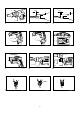
Depth adjustment
Fig.1
The depth can be adjusted by turning the lock ring. Turn
it in "B" direction for less depth and in "A" direction for
more depth. One full turn of the lock ring equals 1.5 mm
change in depth.
Adjust the lock ring so that the distance between the tip
of the locator and the screw head is approximately 1 mm
as shown in the figures. Drive a trial screw into your
material or a piece of duplicate material. If the depth is
still not suitable for the screw, continue adjusting until
you obtain the proper depth setting.
Fig.2
Fig.3
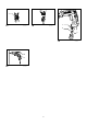
Switch action
Fig.4
CAUTION:
• Before plugging in the tool, always check to see
that the switch trigger actuates properly and
returns to the "OFF" position when released.
To start the tool, simply pull the switch trigger. Tool
speed is increased by increasing pressure on the switch
trigger. Release the switch trigger to stop.
For continuous operation, pull the switch trigger and
then push in the lock button.
To stop the tool from the locked position, pull the switch
trigger fully, then release it.
NOTE:
• Even with the switch on and motor running, the bit
will not rotate until you fit the point of the bit in the
screw head and apply forward pressure to engage
the clutch.