
User Manual


9
FUNCTIONAL DESCRIPTION
CAUTION:
• Always be sure that the tool is switched off and
unplugged before adjusting or checking function
on the tool.
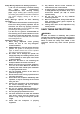
Shaft lock
Fig.1
CAUTION:
• Never actuate the shaft lock when the spindle is
moving. The tool may be damaged.
Press the shaft lock to prevent spindle rotation when
installing or removing accessories.
Switch action
Fig.2
CAUTION:
• Before plugging in the tool, always check to see
that the slide switch actuates properly and returns
to the "OFF" position when the rear of the slide
switch is depressed.
• Switch can be locked in "ON" position for ease of
operator comfort during extended use. Apply
caution when locking tool in "ON" position and
maintain firm grasp on tool.
To start the tool, slide the slide switch toward the "I
(ON)" position by pushing the rear of the slide switch.
For continuous operation, press the front of the slide
switch to lock it.
To stop the tool, press the rear of the slide switch, then
slide it toward the "O (OFF)" position.
Indication lamp
Fig.3
The indication lamp lights up green when the tool is
plugged. If the indication lamp does not light up, the
mains cord or the controller may be defective. The
indication lamp is lit but the tool does not start even if
the tool is switched on, the carbon brushes may be
worn out, or the controller, the motor or the ON/OFF
switch may be defective.
Unintentional restart proof
The tool does not start with the switch being lock-on
even when the tool is plugged.
At this time, the indication lamp flickers red and shows
the unintentional restart proof device is on function.
To cancel the unintentional restart proof, return the slide
switch to "O(OFF)" position.
Speed adjusting dial
Fig.4
The rotating speed can be changed by turning the speed
adjusting dial to a given number setting from 1 to 5.
Higher speed is obtained when the dial is turned in the
direction of number 5. And lower speed is obtained
when it is turned in the direction of number 1.
Refer to the below table for the relationship between the
number settings on the dial and the approximate
rotating speed.
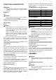
For model GA4040C, GA4540C, GA5040C
Number min
-1
(R.P.M.)
1 2,800
2 4,000
3 6,000
4 8,000
5
11,000
012752
For model GA6040C
Number min
-1
(R.P.M.)
1 4,000
2 5,000
3 6,000
4 7,000
5
9,000
012756
CAUTION:
• If the tool is operated continuously at low speeds
for a long time, the motor will get overloaded and
heated up.
• The speed adjusting dial can be turned only as far
as 5 and back to 1. Do not force it past 5 or 1, or
the speed adjusting function may no longer work.
Electronic function
The tools equipped with electronic function are easy to
operate because of the following features.
Constant speed control
Constant speed control provides fine finish by keeping
the rotating speed constant under the loaded condition.
Soft start feature
Soft start feature suppresses starting shock.
Overload protector
When the load on the tool exceeds admissible levels,
power to the motor is reduced to protect the motor from
overheating. When the load returns to admissible levels,
the tool will operate as normal.
ASSEMBLY
CAUTION:
• Always be sure that the tool is switched off and
unplugged before carrying out any work on the
tool.
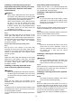
Installing side grip (handle)
Fig.5
CAUTION:
• Always be sure that the side grip is installed
securely before operation.
Screw the side grip securely on the position of the tool
as shown in the figure.