ENGLISH (Original instructions) INSTRUCTION MANUAL Angle Grinder GA7010C GA9010C 005003 DOUBLE INSULATION IMPORTANT: Read Before Using.
ENGLISH (Original instructions) SPECIFICATIONS Model GA7010C GA9010C Depressed center wheel diameter 180 mm 230 mm Spindle thread M14 M14 Rated speed (n) / No load speed (n0) 8400 min-1 6000 min-1 Overall length 453 mm 453 mm Net weight 4.3 kg Safety class 4.5 kg /II • Due to our continuing program of research and development, the specifications herein are subject to change without notice. • Specifications may differ from country to country.
preventive safety measures reduce the risk of starting the power tool accidentally. 21. Store idle power tools out of the reach of children and do not allow persons unfamiliar with the power tool or these instructions to operate the power tool. Power tools are dangerous in the hands of untrained users. 22. Maintain power tools. Check for misalignment or binding of moving parts, breakage of parts and any other condition that may affect the power tool’s operation.
5. 6. 7. 8. 9. 10. 11. 12. Never lay the power tool down until the accessory has come to a complete stop. The spinning accessory may grab the surface and pull the power tool out of your control. 13. Do not run the power tool while carrying it at your side. Accidental contact with the spinning accessory could snag your clothing, pulling the accessory into your body. 14. Regularly clean the power tool’s air vents.
e) Do not attach a saw chain woodcarving blade or toothed saw blade. Such blades create frequent kickback and loss of control Safety Warnings Specific for Grinding and Abrasive Cutting-Off Operations: a) Use only wheel types that are recommended for your power tool and the specific guard designed for the selected wheel. Wheels for which the power tool was not designed cannot be adequately guarded and are unsafe.
24. 25. 26. 27. 28. 29. 30. 31. 32. 33. 34. 35. 36. 37. 38. Do not leave the tool running. Operate the tool only when hand-held. Do not touch the workpiece immediately after operation; it may be extremely hot and could burn your skin. Always be sure that the tool is switched off and unplugged or that the battery cartridge is removed before carrying out any work on the tool. Observe the instructions of the manufacturer for correct mounting and use of wheels. Handle and store wheels with care.
switch trigger. Release the switch trigger to stop. For tool with the lock on and lock-off switch To prevent the switch trigger from accidentally pulled, a lock lever is provided. To start the tool, push in the lock lever and then pull the switch trigger. Release the switch trigger to stop. For continuous operation, push in the lock lever, pull the switch trigger and then push the lock lever further in. To stop the tool from the locked position, pull the switch trigger fully, then release it.
Loosen the lever on the wheel guard. Mount the wheel guard with the protrusion on the wheel guard band aligned with the notch on the bearing box. Then rotate the wheel guard around to the position shown in the figure. Tighten the lever to fasten the wheel guard. If the lever is too tight or too loose to fasten the wheel guard, loosen or tighten the nut by spanner to adjust the tightening of the wheel guard band. To remove wheel guard, follow the installation procedure in reverse.
and then apply the wheel or disc to the workpiece. In general, keep the edge of the wheel or disc at an angle of about 15 degrees to the workpiece surface. During the break-in period with a new wheel, do not work the grinder in the B direction or it will cut into the workpiece. Once the edge of the wheel has been rounded off by use, the wheel may be worked in both A and B direction. wheel brush could increase potential for injury from contact with broken wires.
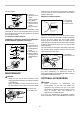
onto the spindle. The tool and its air vents have to be kept clean. Regularly clean the tool's air vents or whenever the vents start to become obstructed. 1. Lock nut 2. Abrasive cut-off wheel/ diamond wheel 3. Inner flange 4. Wheel guard for abrasive cut-off wheel/ diamond wheel 1 2 3 4 Replacing carbon brushes 1. Commutator 2. Insulating tip 3.
1 2 6 6 10 2 3 3 7 11 13 8 12 8 4 5 5 14 9 5 1 Side grip 2 Wheel guard for Depressed center grinding wheel/Multi-disc / Wire wheel brush 3 Inner flange / Super flange 4 Depressed center grinding wheel/Multi-disc 5 Lock nut / Ezynut*1 6 Wheel guard for Abrasive cut off wheel / Diamond wheel *2 7 Inner flange 78 (Australia and New Zealand only)*3 8 Abrasive cut off wheel / Diamond wheel 9 Outer flange 78 (Australia and New Zealand only)*3 10 Rubber pad 11 Abrasive disc
Makita Corporation Anjo, Aichi, Japan 884532C914 12 www.makita.