ENGLISH (Original instructions) INSTRUCTION MANUAL Straight Grinder GS5000 GS6000 013595 DOUBLE INSULATION IMPORTANT: Read Before Using.
ENGLISH (Original instructions) SPECIFICATIONS Model GS5000 GS6000 Maximum wheel capacity (diameter x thickness) 125 mm × 20 mm 150 mm × 20 mm Spindle thread M14 or 1/2" (country specific) No load speed (min-1) Overall length Net weight 5,600 With support cover 590 mm 590 mm Without support cover 588 mm 588 mm With support cover 5.0 kg 5.2 kg Without support cover 4.9 kg 5.
Power tool use and care 18. Do not force the power tool. Use the correct power tool for your application. The correct power tool will do the job better and safer at the rate for which it was designed. 19. Do not use the power tool if the switch does not turn it on and off. Any power tool that cannot be controlled with the switch is dangerous and must be repaired. 20.
GEB108-3 protectors, gloves and workshop apron capable of stopping small abrasive or workpiece fragments. The eye protection must be capable of stopping flying debris generated by various operations. The dust mask or respirator must be capable of filtrating particles generated by your operation. Prolonged exposure to high intensity noise may cause hearing loss. 9. Keep bystanders a safe distance away from work area. Anyone entering the work area must wear personal protective equipment.
Flanges for cut-off wheels may be different from grinding wheel flanges. f) Do not use worn down wheels from larger power tools. Wheel intended for larger power tool is not suitable for the higher speed of a smaller tool and may burst. Additional Safety Warnings: 17. Be careful not to damage the spindle, the flange (especially the installing surface) or the lock nut. Damage to these parts could result in wheel breakage. 18. Make sure the wheel is not contacting the workpiece before the switch is turned on.
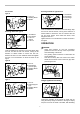
ASSEMBLY FUNCTIONAL DESCRIPTION • CAUTION: Always be sure that the tool is switched off and unplugged before adjusting or checking function on the tool. • CAUTION: Always be sure that the tool is switched off and unplugged before carrying out any work on the tool. Switch action 1 1. Switch trigger 2. Lock lever 5 2 1. Hex wrench 2. Hex bolt 3. Hex lock nut 4. Tighten 5.
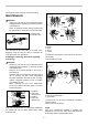
Securing method for type B and C For all tools Type A 3 2 1. Screwdriver 2. Hex wrench 3. Inner flange 4. Hex nut 1 1. Lock nut 2. Grinding wheel 3. Spindle 2 3 4 1 013670 Insert screwdriver into the hole in the inner flange. Grip the hex nut with the wrench, turning in the direction of wheel rotation to loosen the hex nut. Remove the hex nut and outer flange. Then install the wheel, outer flange and hex nut. Tighten the hex nut in the direction of arrow as shown in the figure.
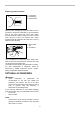
it through the eyelet on the top of the tool housing. 2 MAINTENANCE • • 5 1 CAUTION: Always be sure that the tool is switched off and unplugged before attempting to perform inspection or maintenance. Never use gasoline, benzine, thinner, alcohol or the like. Discoloration, deformation or cracks may result. 4 4 3 2 5 1 1. Exhaust vent 2. Inhalation vent 1 3 2 1. Hook B 2. Hook A 3. Rib A 4. Vent A 5. vent B 013614 The tool and its air vents have to be kept clean.
Replacing carbon brushes 2 1. Commutator 2. Insulating tip 3. Carbon brush 1 3 001146 When the resin insulating tip inside the carbon brush is exposed to contact the commutator, it will automatically shut off the motor. When this occurs, both carbon brushes should be replaced. Keep the carbon brushes clean and free to slip in the holders. Both carbon brushes should be replaced at the same time. Use only identical carbon brushes. 1. Brush holder cap 2.
Makita Corporation 885199-0 12 www.makita.