
Operation Manual

5
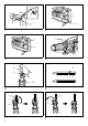
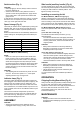
Switch action (Fig. 1)
CAUTION:
• Before plugging in the tool, always check to see that
the tool is switched off.
• Switch can be locked in “ON” position for ease of
operator comfort during extended use. Apply caution
when locking tool in “ON” position and maintain firm
grasp on tool.
To start the tool, push the switch lever “ON (I)” on the left
side of the tool. To stop the tool, push the switch lever
“OFF (O)” on the right side of the tool.
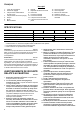
Speed change (Fig. 2)
The blows per minute can be adjusted just by turning the
adjusting dial. This can be done even while the tool is
running. The dial is marked 1 (lowest speed) to 5 (full
speed).
Refer to the table below for the relationship between the
number settings on the adjusting dial and the blows per
minute.
For model HM1317C, HM1317CB only
NOTE:
• Blows at no load per minute becomes smaller than
those on load in order to reduce vibration under no
load, but this does not show trouble. Once operation
starts with a bit against concrete, blows per minute
increase and get to the numbers as shown in the table.
When temperature is low and there is less fluidity in
grease, the tool may not have this function even with
the motor rotating.
CAUTION:
• The adjusting dial can be turned only as far as 5 and
back to 1. Do not force it past 5 or 1, or the speed
adjusting function may no longer work.
Indicator lamp (Fig. 3)
The green power-ON indicator lamp lights up when the
tool is plugged. If the indicator lamp does not light up, the
mains cord or the controller may be malfunction. The
indicator lamp is lit but the tool does not start even if the
tool is switched on, the carbon brushes may be worn out,
or the controller, the motor or the ON/OFF switch may be
malfunction.
The red service indicator lamp flickers up when the
carbon brushes are nearly worn out to indicate that the
tool needs servicing. After approx. 8 hours of use, the
motor will automatically be shut off.
ASSEMBLY
CAUTION:
• Always be sure that the tool is switched off and
unplugged before carrying out any work on the tool.
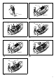
Side handle (auxiliary handle) (Fig. 4)
The side handle can be swung 360° on the vertical and
secured at any desired position. Just loosen the clamp nut
to swing the side handle to a desired position. Then
tighten the clamp nut securely.
Installing or removing the bit
For Model HM1307C, HM1317C only (Fig. 5)
With the notched portion on the shank of the bit facing
toward the tool retainer, insert the bit into the tool holder
as far as it will go. Then pull out and turn the tool retainer
180° to secure the bit. After installing, always make sure
that the bit is securely held in place by trying to pull it out.
For Model HM1307CB, HM1317CB only (Fig. 6)
This tool accepts bits either with or without a collar on its
shank.
(1) For bits with a collar (Fig. 7)
To install the bit, follow either procedure (1) or (2)
described below.
Pivot the tool retainer back and slightly downward.
Insert the bit into the tool holder as far as it will go. To
securely retain the bit, return the tool retainer to its
original position.
CAUTION:
• Always assure that the bit is securely retained by
attempting to pull the bit out of the tool holder after
completing the above procedure.
(2) For bits without a collar (Fig. 8)
Pivot the tool retainer forward and slightly downward.
With the notched portion of the bit facing the tool
retainer shaft, insert the bit into the tool holder as far
as it will go. Then pivot the tool retainer further
downward toward the barrel to securely retain the bit.
CAUTION:
• Always assure that the bit is securely retained by
attempting to pull the bit out of the tool holder after
completing the above procedure.
• The bit without a collar cannot be retained by the
method shown in Fig. 7.
To remove the bit, follow the installation procedure in
reverse.
OPERATION
Chipping/Scaling/Demolition (Fig. 9)
Always use the side grip (auxiliary handle) and firmly hold
the tool by both side grip and switch handle during
operations. Turn the tool on and apply slight pressure on
the tool so that the tool will not bounce around,
uncontrolled. Pressing very hard on the tool will not
increase the efficiency.
MAINTENANCE
CAUTION:
• Always be sure that the tool is switched off and
unplugged before attempting to perform inspection or
maintenance.
Number on adjusting dial Blows per minute
5 1,450
4 1,350
3 1,150
2800
1730