GB Rotary Hammer Instruction manual F Marteau rotatif Manuel d’instructions D Bohrhammer Betriebsanleitung I Martello rotativo Istruzioni per l’uso Boorhamer Gebruiksaanwijzing E Martillo rotativo Manual de instrucciones P Martelo perfurador Manual de instruções DK Borehammer Brugsanvisning GR Περιστροφικ δράπανο Οδηγίες χρήσης NL HR2800 HR2810 HR2810T HR2811F HR2811FT
1 2 1 2 4 A B 3 5 3 6 4 8 7 6 9 5 5 6 9 9 7 2 8
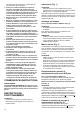
9 10 12 11 9 13 10 14 15 16 17 11 12 16 9 17 13 14 9 18 15 16 3
19 17 18 20 19 20 21 4 22 5 21 22 8 23 7 24 5 23 4 6 6 24 8
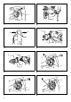
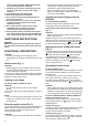
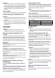
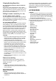
ENGLISH Explanation of general view 1. 2. 3. 4. 5. 6. 7. 8. Switch trigger Lamp Reversing switch lever Quick change chuck for SDS-plus Change cover line Change cover Spindle Quick change drill chuck 9. 10. 11. 12. 13. 14. 15. 16. Action mode changing knob Grip base Side grip Teeth Protrusion Bit shank Bit grease Bit 17. 18. 19. 20. 21. 22. 23. 24.
loosen up the lubrication. Without proper warmup, hammering operation is difficult. 8. Always be sure you have a firm footing. Be sure no one is below when using the tool in high locations. 9. Hold the tool firmly with both hands. 10. Keep hands away from moving parts. 11. Do not leave the tool running. Operate the tool only when hand-held. 12. Do not point the tool at any one in the area when operating. The bit could fly out and injure someone seriously. 13.
CAUTION: • Do not rotate the action mode changing knob when the tool is running under load. The tool will be damaged. • To avoid rapid wear on the mode change mechanism, be sure that the action mode changing knob is always positively located in one of the three action mode positions. Torque limiter The torque limiter will actuate when a certain torque level is reached. The motor will disengage from the output shaft. When this happens, the bit will stop turning.
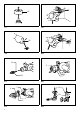
Chipping/Scaling/Demolition For models HR2810, HR2810T, HR2811F, HR2811FT only (Fig. 20) Set the action mode changing knob to the symbol. Hold the tool firmly with both hands. Turn the tool on and apply slight pressure on the tool so that the tool will not bounce around, uncontrolled. Pressing very hard on the tool will not increase the efficiency. Drilling in wood or metal (Fig. 21 – 24) For Model HR2800, HR28010, HR2810F Use the optional drill chuck assembly.
FRANÇAIS Descriptif 1. 2. 3. 4. 5. 6. 7. 8. Gâchette Lampe Levier de l’inverseur Mandrin à remplacement rapide pour SDS-plus Ligne du couvercle de remplacement Couvercle de remplacement Axe 9. 10. 11. 12. 13. 14. 15. Mandrin de perçage à remplacement rapide Bouton de changement de mode Base de la poignée Poignée latérale Dents Partie saillante Arbre du foret Graisse à foret 16. 17. 18. 19. 20. 21. 22. 23. 24.
exposées de l’outil sous tension, causant ainsi un choc électrique chez l’utilisateur. 4. Portez une coiffure résistante (un casque de sécurité), des lunettes de sécurité et/ou une visière. Les lunettes ordinaires et les lunettes de soleil NE sont PAS des lunettes de sécurité. Nous vous recommandons également de porter un masque anti-poussières et des gants très épais. 5. Assurez-vous que le foret est bien serré avant d’utiliser l’outil. 6.
remplacement rapide et placez la ligne en face du symbole . Placez le mandrin de perçage à remplacement rapide sur l’axe de l’outil. Saisissez le couvercle de remplacement du mandrin de perçage à remplacement rapide et tournez la ligne du couvercle de remplacement pour l’aligner sur le symbole jusqu’à ce qu’un déclic clair retentisse. Sélection du mode de fonctionnement Pour le modèle HR2800 (Fig. 6) Cet outil est doté d’un bouton de changement de mode.
Collecteur de poussières (Fig. 17) Utilisez le collecteur de poussières pour éviter que les poussières ne tombent de l’outil et sur vous lors des travaux de perçage au-dessus de la tête. Fixez le collecteur de poussières au foret comme indiqué sur la figure. Les tailles de foret qui permettent de fixer le collecteur de poussières sont les suivantes.
doivent être effectués dans un centre de service aprèsvente Makita agréé, exclusivement avec des pièces de rechange Makita. ACCESSOIRES ATTENTION : • Ces accessoires ou pièces complémentaires sont recommandés pour l’utilisation avec l’outil Makita spécifié dans ce manuel. L’utilisation de tout autre accessoire ou pièce complémentaire comporte un risque de blessures. Utilisez uniquement l’accessoire ou la pièce complémentaire dans le but spécifié.
DEUTSCH Erklärung der Gesamtdarstellung 1. 2. 3. 4. 5. 6. 7. 8. 9. Auslöseschaltung Lampe Umschalthebel Schnellwechselfutter für SDSPlus Markierung der Wechselhülse Wechselhülse Spindel Schnellwechselbohrfutter 10. 11. 12. 13. 14. 15. 16. Drehknopf zum Wechsel der Aktionsbetriebsart Grifffläche Seitenzusatzgriff Zähne Vorsprung Aufnahmeschaft Bohrer-/Meißelfett Einsatz 17. 18. 19. 20. 21. 22. 23. 24.
berühren kann. Der Kontakt mit einem Strom führenden Kabel leitet diesen an die metallenen Teile des Werkzeugs weiter und verursacht einen Stromschlag beim Bediener. 4. Tragen Sie einen Sicherheitshelm, Sicherheitsgläser und/oder Gesichtsschutz. Bei gewöhnlichen Brillen und Sonnenbrillen handelt es sich NICHT um Sicherheitsgläser. Auch das Tragen dick gefütterter Handschuhe und einer Staubmaske wird empfohlen. 5. Überprüfen Sie vor der Inbetriebnahme, ob der Einsatz fest sitzt. 6.
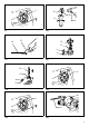
Anbringen des Schnellwechselbohrfutters (Abb. 5) Vergewissern Sie sich, dass die Markierung des Schnellwechselbohrfutters auf dem Symbol steht. Nehmen Sie die Wechselhülse des Schnellwechselbohrfutters in die Hand, und stellen Sie die Markierung auf das Symbol . Setzen Sie das Schnellwechselbohrfutter auf die Spindel des Werkzeugs. Drehen Sie die Wechselhülse des Schnellwechselbohrfutters, bis ihre Markierung auf dem Symbol steht und das Futter mit einem deutlichen Klick einrastet.
Drehen Sie den Drehknopf zum Wechsel der Aktionsbetriebsart auf das Symbol . Überprüfen Sie anschließend durch leichtes Drehen am Einsatz, ob er fest sitzt. (Abb. 15) Tiefenanschlag (Abb. 16) Der Tiefenanschlag ist beim Bohren von Löchern mit einer einheitlichen Bohrtiefe hilfreich. Lockern Sie den Seitengriff und setzen Sie den Tiefenanschlag in die Öffnung am Seitengriff. Stellen Sie den Tiefenanschlag auf die gewünschte Tiefe ein und ziehen Sie den Seitengriff an.
fest, und seien Sie vorsichtig, wenn der Bohrer das Werkstück durchbricht. • Ein festsitzender Einsatz kann einfach wieder herausgezogen werden, indem die Drehrichtung mit dem Umschalter geändert wird. Es kann jedoch zu einem abrupten Rückschlag des Werkzeugs kommen, wenn Sie es nicht ganz fest halten. • Befestigen Sie kleine Werkstücke immer in einem Schraubstock oder einer ähnlichen Haltevorrichtung.
ITALIANO Spiegazione della vista generale 1. 2. 3. 4. 5. 6. 7. 8. 9. Interruttore Lampada Leva di inversione della rotazione Mandrino a cambio rapido per SDS-plus Base del coperchio di cambio Coperchio di cambio Mandrino Mandrino di perforazione a cambio rapido 10. 11. 12. 13. 14. 15. 16. 17. Manopola per la modifica della modalità di azione Base dell'impugnatura Impugnatura laterale Denti Sporgenza Gambo della punta Grasso per punte Punta Copertura del mandrino 18. 19. 20. 21. 22. 23. 24.
parti metalliche esposte dell'utensile si trovino anch'esse sotto tensione provocando scosse elettriche all'operatore. 4. Indossare un elmetto (casco di sicurezza), occhiali di sicurezza e/o visiere protettrici. I comuni occhiali da vista o da sole NON sono occhiali di sicurezza. Si consiglia anche di indossare una maschera antipolvere e guanti imbottiti. 5. Prima di azionare l'utensile, verificare che la punta sia fissata nella posizione corretta. 6.
coperchio di cambio sul simbolo chiaramente uno scatto. fino ad udire provocherebbero la frequente attivazione del limitatore di coppia. Selezione della modalità operativa MONTAGGIO Per il modello HR2800 (Fig. 6) Questo utensile dispone di una manopola che consente di modificare la modalità operativa. Selezionare con la manopola la modalità operativa più appropriata per il lavoro da eseguire.
Scodellino per la polvere (Fig. 17) Utilizzare lo scodellino per la polvere per evitare che la polvere cada sull’utensile o sull’operatore quando si effettuano forature in posizioni elevate, al di sopra della testa. Attaccare lo scodellino per la polvere alla punta come mostrato nella figura. Le dimensioni delle punte a cui si possono attaccare gli scodellini per la polvere sono indicate di seguito.
MANUTENZIONE ATTENZIONE • Prima di effettuare controlli e operazioni di manutenzione, verificare sempre che l'utensile sia spento e scollegato. Per mantenere la SICUREZZA e l’AFFIDABILITÀ del prodotto, le riparazioni, il controllo della spazzola di carbone, le sostituzioni e qualsiasi altra operazione di manutenzione o regolazione devono essere eseguite da un centro di assistenza Makita autorizzato usando sempre ricambi Makita.
NEDERLANDS Verklaring van algemene gegevens 1. 2. 3. 4. 5. 6. 7. 8. 9. 10. 11. 12. 13. 14. 15. 16. Aan/uit-schakelaar Lamp Omkeerschakelaarknop Snelwisselkop voor SDS-plus Streep op wisselmof Wisselmof As Snelwisselboorkop Werkingsfunctie-keuzeknop Basis van de zijhandgreep Zijhandgreep Tanden Uitsteeksel Boorschacht Boorvet Boor 17. 18. 19. 20. 21. 22. 23. 24.
met onder spanning staande draden, zullen de nietgeïsoleerde metalen delen van het gereedschap onder spanning komen te staan zodat de gebruiker een elektrische schok kan krijgen. 4. Draag een veiligheidshelm, veiligheidsbril en/of gezichtsbescherming. Een gewone bril of een zonnebril is GEEN veiligheidsbril. Het wordt tevens sterk aanbevolen een stofmasker en dik gevoerde handschoenen te dragen. 5. Controleer dat het boortje stevig op zijn plaats is vastgezet voordat u het gereedschap gebruikt. 6.
De snelwisselboorkop aanbrengen (zie afb. 5) Controleer of de streep op de snelwisselboorkop bij het symbool staat. Pak de wisselmof van de snelwisselboorkop vast en zet de streep bij het symbool . Zet de snelwisselboorkop op de as van het gereedschap. Pak de wisselmof van de snelwisselboorkop en draai de streep op de wisselmof naar het symbool totdat een duidelijke klik wordt gehoord. De werkingsfunctie selecteren Voor model HR2800 (zie afb.
Diepteaanslag (zie afb. 16) Afbikken en slopen De diepteaanslag is handig voor het boren van gaten van gelijke diepte. Maak de zijhandgreep los en steek de diepteaanslag in het gat in de zijhandgreep. Stel de diepteaanslag af op de gewenste diepte en zet de zijhandgreep vast. OPMERKING: • De diepteaanslag kan niet worden gebruikt in de positie waarbij deze tegen het tandwielhuis aanstoot. Alleen voor modellen HR2810, HR2810T, HR2811F en HR2811FT (zie afb.
ONDERHOUD LET OP: • Zorg er altijd voor dat het gereedschap is uitgeschakeld en de stekker uit het stopcontact is getrokken, voordat u een inspectie of onderhoud uitvoert. Om de VEILIGHEID en BETROUWBAARHEID van het gereedschap te handhaven, dienen alle reparaties, controle en vervanging van de koolborstels, onderhoud en afstellingen te worden uitgevoerd door een erkend Makita-servicecentrum, en altijd met gebruikmaking van originele Makita-vervangingsonderdelen.
ESPAÑOL Descripción y visión general 1. 2. 3. 4. 5. 6. 7. 8. 9. Interruptor disparador Lámpara Palanca del interruptor de inversión Mandril de cambio rápido para SDS-plus Línea de la cubierta de cambio Cubierta de cambio Husillo Mandril de cambio rápido de broca 10. 11. 12. 13. 14. 15. 16. 17. 18. Pomo de cambio de modo de acción Base de la empuñadura Mango lateral Dientes Saliente Espiga de la broca Grasa para brocas Broca Cubierta del mandril Calibre de profundidad 19. 20. 21. 22. 23. 24.
operación en que la herramienta de corte pueda entrar en contacto con cables ocultos o con su propio cable. Si entra en contacto con un cable con corriente, las piezas metálicas expuestas se cargarán también de corriente y el operario puede recibir una descarga. 4. Póngase un casco de seguridad, gafas de seguridad y/o una careta protectora. Las gafas normales o de sol NO son gafas de seguridad. También se recomienda encarecidamente que utilice una mascarilla antipolvo y guantes gruesos acolchados. 5.
Sujete la cubierta de cambio del mandril de cambio rápido para SDS-plus y gírela en la dirección de la flecha hasta que la línea de la cubierta de cambio se mueva desde el símbolo hasta el símbolo . Tire con fuerza en la dirección de la flecha. Limitador de par de apriete Acoplamiento del mandril de cambio rápido de broca (Fig. 5) PRECAUCIÓN: • Desconecte la herramienta tan pronto como actúe el limitador de par de apriete. Ello evitará que la herramienta se desgaste prematuramente.
Gire el pomo de cambio del modo de acción al símbolo . Compruebe que la broca ha quedado bien sujeta; para ello, gírela ligeramente. (Fig. 15) Calibre de profundidad (Fig. 16) El calibre de profundidad es muy útil para realizar agujeros de profundidad uniforme. Afloje la empuñadura lateral e introduzca el calibre de profundidad en el agujero de la empuñadura. Ajuste el calibre a la profundidad deseada y apriete la empuñadura lateral.
• Sujete siempre las piezas de trabajo pequeñas en una prensa de tornillo o un dispositivo de sujeción similar. Taladrado con la broca de diamante Cuando realice operaciones de perforación con brocas de punta de diamante, coloque siempre la palanca de cambio en la posición para girar solamente. PRECAUCIÓN: • Si realiza operaciones de perforación con una broca de punta de diamante utilizando el "giro con percusión", la broca de punta de diamante puede resultar dañada.
PORTUGUÊS Descrição geral 1. 2. 3. 4. 5. 6. 7. 8. 9. Gatilho Lâmpada Interruptor de inversão de rotação Mandril de substituição rápida para brocas SDS-plus Linha indicadora da cobertura de substituição Cobertura de substituição Fuso Mandril de broca de substituição rápida 10. 11. 12. 13. 14. 15. 16. 17. 18. Manípulo de mudança do modo de funcionamento Base do apoio Apoio lateral Dentes Saliência Haste da broca Lubrificante para brocas Broca Cobertura do mandril Medidor de profundidade 19. 20. 21. 22.
2. Utilize as pegas auxiliares fornecidas com a ferramenta. A perda de controlo pode provocar ferimentos. 3. Quando executar operações em que os acessórios de corte possam entrar em contacto com fios eléctricos ocultos ou com o próprio cabo eléctrico da ferramenta, tenha o cuidado de tocar apenas nas superfícies isoladas desses acessórios. O contacto com um fio eléctrico ligado à corrente pode electrificar as peças de metal da ferramenta e causar um choque. 4.
substituição rápida e coloque a linha indicadora no símbolo . Coloque o mandril de broca de substituição rápida no fuso da ferramenta. Segure a cobertura de substituição do mandril de broca de substituição rápida e rode a linha indicadora da cobertura de substituição para o símbolo até ouvir um estalido. Seleccionar o modo de funcionamento Para o modelo HR2800 (Fig. 6) Esta ferramenta possui um manípulo que permite seleccionar o modo de funcionamento.
apoio. Ajuste o medidor de profundidade para a profundidade desejada e aperte o apoio lateral. NOTA: • O medidor de profundidade não pode ser usado na posição em que bate contra o compartimento do motor. Recipiente de pó (Fig. 17) Use o recipiente de pó para impedir que entre pó na ferramenta ou que lhe caia pó em cima ao efectuar perfurações na vertical. Encaixe o recipiente de pó na broca, tal como indicado na figura.
posição para usar a função de “perfuração convencional”. PRECAUÇÃO: • Se efectuar perfurações com coroa de diamante utilizando a função de “perfuração com percussão”, a broca de coroa de diamante pode ficar danificada. MANUTENÇÃO PRECAUÇÃO: • Certifique-se sempre de que a ferramenta está desligada no interruptor e da tomada antes de inspeccionar ou fazer a manutenção da ferramenta.
DANSK Forklaring til generel oversigt 1. 2. 3. 4. 5. 6. 7. 8. 9. 10. 11. 12. 13. 14. 15. 16. 17. Kontaktgreb Lampe Skiftekontakthåndtag Hurtig udskiftelig patron til SDSplus Udskift dæklinje Udskift dæksel Spindel Hurtig udskiftelig borepatron 18. 19. 20. 21. 22. 23. 24.
beskyttelsesbriller. Det anbefales desuden kraftigt at bære støvmaske og kraftigt polstrede handsker. 5. Kontroller, at spidsen sidder godt fast før brug. 6. Værktøjet er designet til at forårsage vibration ved normal brug. Skruer kan nemt løsne sig og medføre et nedbrud eller en ulykke. Kontroller før brug, at skruerne sidder stramt. 7. Under kolde forhold, eller når værktøjet ikke har været anvendt i længere tid, skal De lade værktøjet varme op et stykke tid ved at lade det køre i tomgang.
Til modeller HR2810, HR2810T, HR2811F, HR2811FT Rotation med slag (Fig. 7) Ved boring i beton, murværk osv. skal funktionsknappen drejes til -symbolet. Brug en bit med wolframkarbidforstærkning. Kun rotation (Fig. 8) Ved boring i træ, metal eller plastikmaterialer skal låseknappen trykkes ned og funktionsknappen drejes til -symbolet. Brug en snegleborsbit eller en træbit. Kun slag (Fig. 9) Ved mejslings-, afbanknings- eller nedrivningsbetjeninger skal funktionsknappen drejes til -symbolet.
kontakthåndtaget under betjening. Hvis De ikke gør dette, kan De miste kontrollen med maskinen, hvilket kan forårsage alvorlig personskade. BEMÆRK: Excentricitet i spidsrotationen kan forekomme, når værktøjet betjenes uden belastning. Værktøjet centrerer sig selv under betjening. Dette indvirker ikke på præcisionen under boring. Udblæsningskolbe (fås som tilbehør) (Fig. 19) Når hullet er boret, kan De bruge udblæsningskolben til at fjerne støv fra hullet.
ΕΛΛΗΝΙΚΑ Περιγραφή γενικής ψης 1. 2. 3. 4. 5. 6. 7. 8. Σκανδάλη-διακ πτης Λάμπα Αναστροφικ Κεφαλή ταχείας αλλαγής για SDS-plus Γραμμή καλύμματος αλλαγής Κάλυμμα αλλαγής Άτρακτος Κεφαλή δραπάνου ταχείας αλλαγής 9. 10. 11. 12. 13. 14. 15. 16. 17. 18. Λαβή αλλαγής τρ που δράσης Βάση λαβής Πλαϊνή λαβή Δ ντια Προεξοχή Κολάρο μύτης Γράσο για μύτες Μύτη Κάλυμμα κεφαλής Μετρητής βάθους 19. 20. 21. 22. 23. 24.
ελέγχου μπορεί να προκαλέσει προσωπικ τραυματισμ . 3. Να κρατάτε τα ηλεκτρικά εργαλεία απ τις λαβές με μ νωση ταν εκτελείτε εργασίες κατά τις οποίες το κοπτικ εργαλείο μπορεί να έρθει σε επαφή με κρυμμένα καλώδια ή με το ίδιο του το καλώδιο. Αν το εργαλείο έρθει σε επαφή με κάποιο ηλεκτροφ ρο καλώδιο, μπορεί τα εκτεθειμένα μεταλλικά μέρη του εργαλείου να γίνουν κι αυτά ηλεκτροφ ρα και να προκληθεί ηλεκτροπληξία στο χειριστή. 4. Να φοράτε κράνος ασφάλειας, γυαλιά ασφάλειας ή/και προσωπίδα.
Αφαίρεση της κεφαλής ταχείας αλλαγής για SDSplus (Εικ. 4) Χρησιμοποιήστε βελ νι, ψυχρ καλέμι, καλέμι σφυροκοπήματος, κτλ. ΠΡΟΣΟΧΗ: • Πριν αφαιρέσετε την κεφαλή ταχείας αλλαγής για SDS-plus, να αφαιρείτε πάντα τη μύτη. Πιάστε το κάλυμμα αλλαγής της κεφαλής ταχείας αλλαγής για SDS-plus και περιστρέψτε προς την κατεύθυνση που δείχνει το βέλος έως του η γραμμή καλύμματος αλλαγής μετακινηθεί απ το σύμβολο στο σύμβολο . Τραβήξτε με δύναμη προς την κατεύθυνση του βέλους.
Μετά την τοποθέτηση, να προσπαθείτε πάντοτε να τραβήξετε τη μύτη για να βεβαιωθείτε τι αυτή είναι ασφαλισμένη στη θέση της. Για να αφαιρέσετε τη μύτη, τραβήξτε προς τα κάτω το κάλυμμα κεφαλής έως το τέρμα και τραβήξτε τη μύτη προς τα έξω. (Εικ. 13) Κλίση μύτης (κατά το καλέμισμα, ξύσιμο ή ξήλωμα) διατηρείτε το εργαλείο στη θέση του και να αποφεύγετε την ολίσθησή του απ την οπή. Μην ασκείτε περισσ τερη πίεση σε περίπτωση που η οπή φράξει με θραύσματα ή σωματίδια.
το δακτύλιο και στρέψτε το περίβλημα αριστερ στροφα για να ανοίξετε τις σιαγ νες κεφαλής. Τοποθετήστε τη μύτη στην κεφαλή έως το τέρμα. Κρατήστε καλά το δακτύλιο και στρέψτε το περίβλημα δεξι στροφα για να σφίξετε την κεφαλή. Για να βγάλετε τη μύτη, κρατήστε το δακτύλιο και στρέψτε το περίβλημα αριστερ στροφα. Θέστε τη λαβή αλλαγής τρ που δράσης στο σύμβολο . Μπορείτε να τρυπήσετε διάμετρο έως 13 χλστ σε μέταλλο και έως 32 χλστ σε ξύλο.
ENGLISH EC-DECLARATION OF CONFORMITY ITALIANO ENH101-7 Model; HR2800, HR2810, HR2810T, HR2811F, HR2811FT We declare under our sole responsibility that this product is in compliance with the following standards of standardized documents; EN60745, EN55014, EN61000 in accordance with Council Directives, 2004/108/EC, 98/37/EC.
PORTUGUÊS ΕΛΛΗΝΙΚΑ EC-DECLARAÇÃO DE CONFORMIDADE ENH101-7 Modelo; HR2800, HR2810, HR2810T, HR2811F, HR2811FT Declaramos, sob a nossa única responsabilidade, que este produto está em conformidade com as seguintes normas de documentos normalizados; EN60745, EN55014, EN61000 em conformidade com as Directivas do Conselho, 2004/108/EC, 98/37/EC.
ENGLISH ITALIANO For Model HR2800 For European countries only ENG102-1 Noise The typical A-weighted noise level determined according to 607452-6: Sound pressure level (LpA): 89 dB (A) Sound power level (LWA): 100 dB (A) Uncertainty (K): 3 dB (A) Wear ear protection Per il modello HR2800 Solo per i paesi europei ENG102-1 Rumorosità I tipici livelli di rumore ponderati "A" determinati secondo la direttiva 60745-2-6: Livello di pressione sonora (LpA): 89 dB (A) Livello di potenza sonora (LWA): 100 dB (A) Va
PORTUGUÊS ΕΛΛΗΝΙΚΑ Para o modelo HR2800 Apenas para os países europeus ENG102-1 Ruído Os níveis sonoros dB (A) típicos determinados segundo a norma 60745-2-6 são: Nível de pressão sonora (LpA): 89 dB (A) Nível de potência sonora (LWA): 100 dB (A) Imprecisão (K): 3 dB (A) Use uma protecção para os ouvidos Για το μοντέλο HR2800 Για ευρωπαϊκές χώρες μ νο ENG102-1 Θ ρυβος Το σύνηθες σταθμισμένο επίπεδο ηχητικής πίεσης που έχει καθοριστεί σύμφωνα με 60745-2-6: Επίπεδο ηχητικής πίεσης (LpA): 89 dB (A) Επίπεδο
ENGLISH ITALIANO For Model HR2800 For European countries only Vibration ENG217-1 The vibration total value (tri-axial vector sum) determined according to EN60745-2-6: Work mode: hammer drilling into concrete, 10 mm diameter and 100 mm depth Vibration emission (ah,HD): 20 m/s2 Uncertainty (K): 1.
PORTUGUÊS ΕΛΛΗΝΙΚΑ Para o modelo HR2800 Apenas para os países europeus Vibração ENG217-1 O valor total da vibração (soma vectorial triaxial) determinado segundo a norma EN60745-2-6 é: Modo de trabalho: martelo a perfurar betão, 10 mm de diâmetro e 100 mm de profundidade Emissão de vibração (ah,HD): 20 m/s2 Imprecisão (K): 1,5 m/s2 Για το μοντέλο HR2800 Για ευρωπαϊκές χώρες μ νο Κραδασμοί ENG217-1 Η συνολική τιμή δ νησης (διανυσματικ άθροισμα τριών αξ νων) που έχει καθοριστεί σύμφωνα με την EN60745-2-6:
ENGLISH ITALIANO For Model HR2810, 2810T For European countries only ENG102-1 Noise The typical A-weighted noise level determined according to 607452-6: Sound pressure level (LpA): 89 dB (A) Sound power level (LWA): 100 dB (A) Uncertainty (K): 3 dB (A) Wear ear protection Per il modello HR2810, 2810T Solo per i paesi europei ENG102-1 Rumorosità I tipici livelli di rumore ponderati "A" determinati secondo la direttiva 60745-2-6: Livello di pressione sonora (LpA): 89 dB (A) Livello di potenza sonora (LWA):
PORTUGUÊS ΕΛΛΗΝΙΚΑ Para os modelos HR2810 e 2810T Apenas para os países europeus Ruído Os níveis sonoros dB (A) típicos determinados segundo a norma 60745-2-6 são: Nível de pressão sonora (LpA): 89 dB (A) Nível de potência sonora (LWA): 100 dB (A) Imprecisão (K): 3 dB (A) Use uma protecção para os ouvidos ENG102-1 Για τα μοντέλα HR2810, 2810T Για ευρωπαϊκές χώρες μ νο ENG102-1 Θ ρυβος Το σύνηθες σταθμισμένο επίπεδο ηχητικής πίεσης που έχει καθοριστεί σύμφωνα με 60745-2-6: Επίπεδο ηχητικής πίεσης (LpA):
ENGLISH ITALIANO For Model HR2810, 2810T For European countries only Vibration ENG215-1 The vibration total value (tri-axial vector sum) determined according to EN60745-2-6: Work mode: chiseling function Vibration emission (ah,CHeq): 15.5 m/s2 Uncertainty (K): 1.
PORTUGUÊS ΕΛΛΗΝΙΚΑ Para os modelos HR2810 e 2810T Apenas para os países europeus Vibração ENG215-1 O valor total da vibração (soma vectorial triaxial) determinado segundo a norma EN60745-2-6 é: Modo de trabalho: função de cinzelagem Emissão de vibração (ah,CHeq): 15,5 m/s2 Imprecisão (K): 1,5 m/s2 Για τα μοντέλα HR2810, 2810T Για ευρωπαϊκές χώρες μ νο Κραδασμοί ENG215-1 Η συνολική τιμή δ νησης (διανυσματικ άθροισμα τριών αξ νων) που έχει καθοριστεί σύμφωνα με την EN60745-2-6: Κατάσταση λειτουργίας: καλέ
ENGLISH ITALIANO For Model HR2811F, HR2811FT For European countries only ENG102-1 Noise The typical A-weighted noise level determined according to 607452-6: Sound pressure level (LpA): 90 dB (A) Sound power level (LWA): 101 dB (A) Uncertainty (K): 3 dB (A) Wear ear protection Per i modelli HR2811F, HR2811FT Solo per i paesi europei ENG102-1 Rumorosità Il tipico livello di rumore ponderato "A" è determinato in conformità con la norma EN60745-2-6: Livello di pressione sonora (LpA): 90 dB (A) Livello di pot
PORTUGUÊS ΕΛΛΗΝΙΚΑ Para os modelos HR2811F e HR2811FT Apenas para os países europeus ENG102-1 Ruído Os níveis sonoros dB (A) típicos determinados segundo a norma 60745-2-6 são: Nível de pressão sonora (LpA): 90 dB (A) Nível de potência sonora (LWA): 101 dB (A) Imprecisão (K): 3 dB (A) Use uma protecção para os ouvidos Για τα μοντέλα HR2811F, HR2811FT Για ευρωπαϊκές χώρες μ νο ENG102-1 Θ ρυβος Το σύνηθες σταθμισμένο επίπεδο θορύβου που έχει καθοριστεί σύμφωνα με την 60745-2-6: Επίπεδο ηχητικής πίεσης (LpA
ENGLISH ITALIANO For Model HR2811F, HR2811FT For European countries only Vibration ENG215-1 The vibration total value (tri-axial vector sum) determined according to EN60745-2-6: Work mode: chiseling function Vibration emission (ah,CHeq): 11.5 m/s2 Uncertainty (K): 1.
PORTUGUÊS ΕΛΛΗΝΙΚΑ Para os modelos HR2811F e HR2811FT Apenas para os países europeus Vibração ENG215-1 O valor total da vibração (soma vectorial triaxial) determinado segundo a norma EN60745-2-6 é: Modo de trabalho: função de cinzelagem Emissão de vibração (ah,CHeq): 11,5 m/s2 Imprecisão (K): 1,5 m/s2 Για τα μοντέλα HR2811F, HR2811FT Για ευρωπαϊκές χώρες μ νο Κραδασμοί ENG215-1 Η συνολική τιμή δ νησης (διανυσματικ άθροισμα τριών αξ νων) που έχει καθοριστεί σύμφωνα με την EN60745-2-6: Κατάσταση λειτουργί
Makita Corporation Anjo, Aichi, Japan 884729-991