
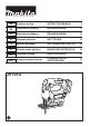
User Manual

9 ENGLISH
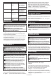
Front ush cuts
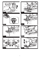
►Fig.13: 1. Hex wrench 2. Bolt 3. Base
Loosentheboltonthebackofthebasewiththehex
wrenchandslidethebaseallthewayback.Then
tightenthebolttosecurethebase.
Cutouts
Cutoutscanbemadewitheitheroftwomethods
“Boringastartinghole”or“Plungecutting”.
Boring a starting hole
►Fig.14
For internal cutouts without a lead-in cut from an edge,
pre-drill a starting hole 12 mm or more in diameter.
Insertthejigsawbladeintothisholetostartyourcut.
Plunge cutting
►Fig.15
Youneednotboreastartingholeormakealead-incut
if you carefully do as follows.
1. Tiltthetooluponthefrontedgeofthebasewith
thejigsawbladepointpositionedjustabovethework-
piece surface.
2. Apply pressure to the tool so that the front edge of
thebasewillnotmovewhenyouswitchonthetooland
gentlylowerthebackendofthetoolslowly.
3. Asthejigsawbladepiercestheworkpiece,slowly
lowerthebaseofthetooldownontotheworkpiece
surface.
4. Complete the cut in the normal manner.
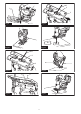
Finishing edges
►Fig.16
Totrimedgesormakedimensionaladjustments,runthe
jigsawbladelightlyalongthecutedges.
Metal cutting
Alwaysuseasuitablecoolant(cuttingoil)whencutting
metal.Failuretodosowillcausesignicantjigsaw
bladewear.Theundersideoftheworkpiececanbe
greased instead of using a coolant.
Dust extraction
►Fig.17: 1. Hose (optional accessory) 2. Dust cover
Cleancuttingoperationscanbeperformedbyconnect-
ing this tool to a Makita vacuum cleaner.
Insertthehoseofthevacuumcleanerintotheholeat
the rear of the tool.
Lowerthedustcoverbeforeoperation.
NOTE:Dustextractioncannotbeperformedwhen
makingbevelcuts.
Rip fence
Optional accessory
CAUTION: Always be sure that the tool is
switched off and the battery cartridge is removed
before installing or removing accessories.
Straight cuts
When repeatedly cutting widths of 160 mm or less, use
of the rip fence will assure fast, clean, straight cuts.
►Fig.18: 1. Rip fence (Guide rule)
Toinstall,inserttheripfenceintotherectangularhole
onthesideofthebasewiththefenceguidefacing
down. Slide the rip fence to the desired cutting width
position,thentightenthebolttosecureit.
►Fig.19: 1. Hex wrench 2. Bolt 3. Fence guide 4. Rip
fence (Guide rule)
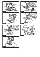
Circular cuts
When cutting circles or arcs of 170 mm or less in radius,
install the rip fence as follows.
►Fig.20: 1. Rip fence (Guide rule)
1. Inserttheripfenceintotherectangularholeonthe
sideofthebasewiththefenceguidefacingup.
2. Insertthecircularguidepinthrougheitherofthe
twoholesonthefenceguide.Screwthethreadedknob
onto the pin to secure the pin.
►Fig.21: 1.Threadedknob2. Fence guide 3. Rip
fence (Guide rule) 4.Pin
3. Slide the rip fence to the desired cutting radius,
andtightenthebolttosecureitinplace.Thenmovethe
baseallthewayforward.
NOTE:AlwaysusejigsawbladesNo.B-17,B-18,
B-26 or B-27 when cutting circles or arcs.
Anti-splintering device
Optional accessory, only for aluminum base model
CAUTION: The anti-splintering device cannot
be used when making bevel cuts.
►Fig.22: 1. Base 2. Anti-splintering device
For splinter-free cuts, the anti-splintering device can
beused.Toinstalltheanti-splinteringdevice,movethe
toolbaseallthewayforwardandtitfromthebackof
toolbase.
When you use the cover plate, install the anti-splintering
device onto the cover plate.
Cover plate
Optional accessory, only for aluminum base model
►Fig.23: 1. Cover plate 2. Base
Use the cover plate when cutting decorative veneers,
plastics,etc.Itprotectssensitiveordelicatesurfaces
fromdamage.Fititonthebackofthetoolbase.