
Use and Care Manual


11 ENGLISH
1
2
3
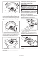
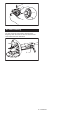
► 1. Wheel guard 2. Bearing box 3. Screw
For tool with clamp lever type wheel guard
Loosen the screw, and then pull the lever in the direc-
tion of the arrow. Mount the wheel guard with the protru-
sions on the wheel guard band aligned with the notches
on the bearing box. Then rotate the wheel guard to such
an angle that it can protect the operator according to
work.
1
2
3
4
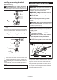
► 1. Wheel guard 2. Bearing box 3. Screw 4. Lever
Pull the lever in direction of the arrow. Then tighten the
wheel guard with fastening the screw. Be sure to tighten
the screw securely. The setting angle of the wheel
guard can be adjusted with the lever.
1
2
► 1. Screw 2. Lever
To remove wheel guard, follow the installation proce-
dure in reverse.
Installing or removing depressed
center wheel or multi-disc
Optional accessory
WARNING: When using a depressed center
wheel or multi-disc, the wheel guard must be
tted on the tool so that the closed side of the
guard always points toward the operator.
CAUTION: Make sure that the mounting part
of the inner ange ts into the inner diameter of
the depressed center wheel / multi-disc perfectly.
Mounting the inner ange on the wrong side may
result in the dangerous vibration.
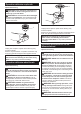
Mount the inner ange onto the spindle.
Make sure to t the dented part of the inner ange onto
the straight part at the bottom of the spindle.
Fit the depressed center wheel / multi-disc on the inner
ange and screw the lock nut onto the spindle.
1
2
4
3
► 1. Lock nut 2. Depressed center wheel 3. Inner
ange 4. Mounting part
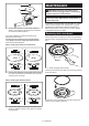
To tighten the lock nut, press the shaft lock rmly so
that the spindle cannot revolve, then use the lock nut
wrench and securely tighten clockwise.
1
2
► 1. Lock nut wrench 2. Shaft lock
To remove the wheel, follow the installation procedure
in reverse.