Slide Compound Saw Equipped with Electric Blade Brake 305 mm (12”) MODEL LS1212 DOUBLE INSULATION I N S T R U C T I O N M A N U A L WARNING: For your personal safety, READ and UNDERSTAND before using. SAVE THESE INSTRUCTIONS FOR FUTURE REFERENCE. w w w. m a k i t a t o o l s.
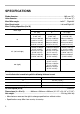
SPECIFICATIONS Blade diameter : ............................................................................................. 305 mm (12”) Hole diameter : ................................................................................................ 25.4 mm (1”) Max. Miter angle : ...................................................................................Left 47° , Right 60° Max. Bevel angle : ...................................................................................
For Your Own Safety Read Instruction Manual Before Operating Tool Save it for future reference USA007-1 GENERAL SAFETY PRECAUTIONS (For All Tools) 1. KNOW YOUR POWER TOOL. Read the owner’s manual carefully. Learn the tool’s applications and limitations, as well as the specific potential hazards peculiar to it. bracelets, or other jewelry which may get caught in moving parts. Nonslip footwear is recommended. Wear protective hair covering to contain long hair. 2. KEEP GUARDS IN PLACE and in working order.
19. CHECK DAMAGED PARTS. Before further use of the tool, a guard or other part that is damaged should be carefully checked to determine that it will operate properly and perform its intended function - check for alignment of moving parts, binding of moving parts, breakage of parts, mounting, and any other conditions that may affect its operation. A guard or other part that is damaged should be properly repaired or replaced. 20. DIRECTION OF FEED.
ADDITIONAL SAFETY RULES USB036-2 DO NOT let comfort or familiarity with product (gained from repeated use) replace strict adherence to slide compound saw safety rules. If you use this tool unsafely or incorrectly, you can suffer serious personal injury. 1. Wear eye protection. 2. Keep hands out of path of saw blade. Avoid contact with any coasting blade. It can still cause severe injury. 3. Do not operate saw without guards in place. Check blade guard for proper closing before each use.
19. Make sure the shaft lock is released before the switch is turned on. such as abrasive wheels may cause an injury. 20. Be sure that the blade does not contact the turn base in the lowest position. 29. NEVER hold workpiece on right side of blade with left hand or vice versa. This is called cross-armed cutting and exposes user to risk of SERIOUS PERSONAL INJURY as shown in the figure. ALWAYS use vise to secure workpiece. 21. Hold the handle firmly.
INSTALLATION 001564 1 Bench mounting When the tool is shipped, the handle is locked in the lowered position by the stopper pin. Release the stopper pin by lowering the handle slightly and pulling the stopper pin. 1. Stopper pin 002224 1 This tool should be bolted with four bolts to a level and stable surface using the bolt holes provided in the tool’s base. This will help prevent tipping and possible injury. 1.
1 If the blade guard is especially dirty and vision through the guard is impaired, use the supplied socket wrench to loosen the hex bolt holding the center cover. Loosen the hex bolt by turning it counterclockwise and raise the blade guard and center cover. With the blade guard so positioned, cleaning can be more completely and efficiently accomplished. When cleaning is complete, reverse procedure above and secure bolt. Do not remove spring holding blade guard.
002226 Maintaining maximum cutting capacity This tool is factory adjusted to provide the maximum cutting capacity for a 305 mm (12”) saw blade. 1 When installing a new blade, always check the lower limit position of the blade and if necessary, adjust it as follows: 2 1. Adjusting bolt 2. Turn Base 001540 2 1 First, unplug the tool. Push the carriage toward the guide fence fully and lower the handle completely.
002227 5 1 2 4 Adjusting the miter angle Loosen the grip by turning counterclockwise. Turn the turn base while pressing down the lock lever. When you have moved the grip to the position where the pointer points to the desired angle on the miter scale, securely tighten the grip clockwise. 3 1. 2. 3. 4. 5. Miter scale Pointer Lock lever Grip Turn base • • 001542 CAUTION: When turning the turn base, be sure to raise the handle fully.
001551 1 3 1. Lock-off button 2. Handle 3. Switch trigger Switch action 2 • CAUTION: Before plugging in the tool, always check to see that the switch trigger actuates properly and returns to the “OFF” position when released. • When not using the tool, remove the lock-off button and store it in a secure place. This prevents unauthorized operation. • Do not pull the switch trigger hard without pressing in the lock-off button. This can cause switch breakage.
ASSEMBLY • 002228 CAUTION: Always be sure that the tool is switched off and unplugged before carrying out any work on the tool. Socket wrench storage The socket wrench is stored as shown in the figure. When using the socket wrench, pull it out of the wrench holder. After using the socket wrench, return it to the wrench holder. 1 2 1. Wrench holder 2.
001533 Press the shaft lock to lock the spindle and use the socket wrench to loosen the hex bolt clockwise. Then remove the hex bolt, outer flange and blade. 001791 To install the blade, mount it carefully onto the spindle, making sure that the direction of the arrow on the surface of the blade matches the direction of the arrow on the blade case.
001536 2 1 Dust bag The use of the dust bag makes cutting operations clean and dust collection easy. To attach the dust bag, fit it onto the dust nozzle. 3 1. Dust nozzle 2. Dust bag 3. Fastener When the dust bag is about half full, remove the dust bag from the tool and pull the fastener out. Empty the dust bag of its contents, tapping it lightly so as to remove particles adhering to the insides which might hamper further collection.
002261 • 1 CAUTION: When performing left bevel cuts, flip the fence over to the left position as shown in the figure. Otherwise, it will contact the blade or a part of the tool, causing possible serious injury to the operator. 1. Sub-fence 002229 Sub-fence R (optional accessory) The sub-fence R can be installed on the right side of the guide fence. Insert the rods of the sub-fence R into the holes in the guide fence. Tighten the screws which come with the sub-fence R to secure the sub-fence R.
002230 The horizontal vise can be installed in two positions on either the left or right side of the base. When performing 15° or greater miter cuts, install the horizontal vise on the side opposite the direction in which the turn base is to be turned. By flipping the vise nut to the left, the vise is released, and rapidly moves in and out. To grip the workpiece, push the vise knob forward until the vise plate contacts the workpiece and flip the vise nut to the right.
OPERATION • 002231 1 1. Knob CAUTION: Before use, be sure to release the handle from the lowered position by pulling the stopper pin. • Make sure the blade is not contacting the workpiece, etc. before the switch is turned on. • Do not apply excessive pressure on the handle when cutting. Too much force may result in overload of the motor and/or decreased cutting efficiency. Push down handle with only as much force as is necessary for smooth cutting and without significant decrease in blade speed.
002232 1 1. Knob 2. Slide (push) cutting (cutting wide workpieces) Loosen the knob counterclockwise so that the carriage can slide freely. Secure the workpiece with the vise. Pull the carriage toward you fully. Switch on the tool without the blade making any contact and wait until the blade attains full speed. Press down the handle and PUSH THE CARRIAGE TOWARD THE GUIDE FENCE AND THROUGH THE WORKPIECE.
• CAUTION: Always be sure that the blade will move down to bevel direction during a bevel cut. Keep hands out of path of saw blade. • During a bevel cut, it may create a condition whereby the piece cut off will come to rest against the side of the blade. If the blade is raised while the blade is still rotating, this piece may be caught by the blade, causing fragments to be scattered which is dangerous. The blade should be raised ONLY after the blade has come to a complete stop.
001555 52∞ 38∞ 45∞ 45∞ 45∞ 1 There are two common types of crown moldings and one type of cove moldings; 52/38° wall angle crown molding, 45° wall angle crown molding and 45° wall angle cove molding. See illustrations. 45∞ 2 3 1. 52/38° type crown molding 2. 45° type crown molding 3. 45° type cove molding 001556 (1) (2) (3) (4) Fig.A 1 2 1. Inside corner 2.
Example: In the case of cutting 52/38° type crown molding for position (1) in Fig. A: • Tilt and secure bevel angle setting to 33.9° LEFT. • Adjust and secure miter angle setting to 31.6° RIGHT. • Lay crown molding with its broad back (hidden) surface down on the turn base with its CEILING CONTACT EDGE against the guide fence on the saw. • The finished piece to be used will always be on the LEFT side of the blade after the cut has been made.
• Lay crown molding with its broad back (hidden) surface down on the turn base with its WALL CONTACT EDGE against the guide fence on the saw. • The finished piece to be used will always be on the RIGHT side of the blade after the cut has been made.
EN0002-1 000031 Ceiling Compound Miter Saw Miter and Bevel Angle Settings Wall 52˚ 38˚ Wall to Crown Molding Angle: 52/38 degrees Wall Angle Bevel Angle Miter Angle (deg.) (deg.) (deg.) 43.0 46.8 60 61 42.8 46.3 62 42.5 45.7 63 42.2 45.1 64 41.9 44.6 65 41.7 44.0 66 41.4 43.5 67 41.1 42.9 68 40.8 42.4 69 40.5 41.9 70 40.2 41.3 71 39.9 40.8 72 39.6 40.3 73 39.3 39.8 74 39.0 39.2 75 38.7 38.7 76 38.4 38.2 77 38.1 37.7 78 37.8 37.2 79 37.4 36.8 80 37.1 36.3 81 36.8 35.8 82 36.5 35.3 83 36.2 34.8 84 35.
EN0003-1 000032 Ceiling Compound Miter Saw Miter and Bevel Angle Settings Wall 45˚ 45˚ Wall to Crown Molding Angle: 45 degrees Wall Angle Bevel Angle Miter Angle (deg.) (deg.) (deg.) 37.8 50.8 60 61 37.5 50.2 62 37.3 49.6 63 37.1 49.1 64 36.8 48.5 65 36.6 48.0 66 36.4 47.4 67 36.1 46.9 68 35.9 46.4 69 35.6 45.8 70 35.4 45.3 71 35.1 44.8 72 34.9 44.2 73 34.6 43.7 74 34.4 43.2 75 34.1 42.7 76 33.9 42.1 77 33.6 41.6 78 33.3 41.1 79 33.1 40.6 80 32.8 40.1 81 32.5 39.6 82 32.3 39.1 83 32.0 38.6 84 31.7 38.
1 002262 Crown molding stoppers (optional accessories) allow easier cuts of crown molding without tilting the saw blade. Install them on the base as shown in the figures. 001560 Position crown molding with its WALL CONTACT EDGE against the guide fence and its CEILING CONTACT EDGE against the crown molding stoppers as shown in the figure. Adjust the crown molding stoppers according to the size of the crown molding. Tighten the screws to secure the crown molding stoppers.
8. Wood facing Use of wood facing helps to assure splinter-free cuts in workpieces. Attach a wood facing to the guide fence using the holes in the guide fence. See the figure concerning the dimensions for a suggested wood facing. 24mm (15/16”) Over 580mm (22-3/4”) 1 105mm 115mm 115mm 105mm (4-1/8”) (4-1/2”) (4-1/2”) (4-1/8”) 1 107-120mm (4-1/4”)-(4-3/4”) 002234 Over 17mm (11/16”) 1. Hole • • CAUTION: Use straight wood of even thickness as the wood facing.
001846 1 3 2 1. Set plate 2. Holder 3. Screw 9. Cutting repetitive lengths When cutting several pieces of stock to the same length, ranging from 300 mm (11 - 3/4”) to 470 mm (18 - 1/2”), use of the set plate (optional accessory) will facilitate more efficient operation. Install the set plate on the holder (optional accessory) as shown in the figure.
001565 Carry the tool by holding both sides of the tool base as shown in the figure. If you remove the holders, dust bag, etc., you can carry the tool more easily. • • MAINTENANCE • CAUTION: Always secure all moving portions before carrying the tool. Stopper pin is for carrying and storage purposes only and not for any cutting operations. CAUTION: Always be sure that the tool is switched off and unplugged before attempting to perform inspection or maintenance.
002237 1 2 Make sure that the pointer points to 0° on the miter scale. If the pointer does not point to 0°, loosen the screw which secures the pointer and adjust the pointer so that it will point to 0°. 3 1. Screw 2. Miter scale 3. Pointer 001569 2. Bevel angle (1) 0° bevel angle Push the carriage toward the guide fence and tighten the knob to secure the carriage. Lower the handle fully and lock it in the lowered position by pushing in the stopper pin. Loosen the lever at the rear of the tool.
001572 1 2 3 Make sure that the two pointers on the arm point to each 0° on the bevel scale on the arm holder. If they do not point to 0°, loosen the screws which secure the pointers and adjust them so that they will point to 0°. 3 1. Bevel scale 2. Screws 3. Pointers 001573 1 2 3 1. Arm holder 2. Right 45° bevel angle adjusting bolt 3. Left 45° bevel angle adjusting bolt 001145 (2) 45° bevel angle Adjust the 45° bevel angle only after performing 0° bevel angle adjustment.
After use • After use, wipe off chips and dust adhering to the tool with a cloth or the like. Keep the blade guard clean according to the directions in the previously covered section titled “Blade guard”. Lubricate the sliding portions with machine oil to prevent rust. • When storing the tool, pull the carriage toward you fully so that the slide pole is thoroughly inserted into the turn base.
Memo 32
Cut First-Class Postage Required Post Office will not deliver without proper postage. Makita U.S.A., Inc.
MAIL THIS PORTION Your answers to the following questions are appreciated. 1. This product was purchased from: Home Center 3. How did you learn about this product: Magazine Radio Hardware/Lumber Store From Dealer Exhibition Tool Distributor Newspaper From Friend Industrial Supply Store Display Previous Usage Construction Supply Catalog Other ( Other ( ) 2. Use of the product is intended for: ) 4.
FACTORY SERVICE CENTERS 1-800-4-MAKITA RETAIN THIS PORTION FOR YOUR RECORDS ARIZONA 3707 E. Broadway Rd., Ste. 6 Phoenix, AZ 85040 (602) 437-2850 FLORIDA 750 East Sample Road Pompano Beach, FL 33064 (954) 781-6333 MISSOURI 9876 Watson Road St. Louis, MO 63126-2221 (314) 909-9889 PENNSYLVANIA 1704 Babcock Blvd. Pittsburgh, PA 15209 (412) 822-7370 CALIFORNIA 41850 Christy St. Fremont, CA 94538-5107 (510) 657-9881 GEORGIA 4680 River Green Parkway NW Duluth, GA 30096 (770) 476-8911 NEBRASKA 4129 S.
WARNING Some dust created by power sanding, sawing, grinding, drilling, and other construction activities contains chemicals known to the State of California to cause cancer, birth defects or other reproductive harm. Some examples of these chemicals are: • lead from lead-based paints, • crystalline silica from bricks and cement and other masonry products, and • arsenic and chromium from chemically-treated lumber. Your risk from these exposures varies, depending on how often you do this type of work.