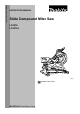
ENGLISH (Original instructions) INSTRUCTION MANUAL Slide Compound Miter Saw LS1216 LS1216L 010049 DOUBLE INSULATION IMPORTANT: Read Before Using.
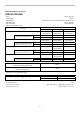
ENGLISH (Original instructions) SPECIFICATIONS Model LS1216/ LS1216L Blade diameter 305 mm European countries: 30 mm, other than European countries: 25.4 mm Hole diameter Max. Miter angle Left 52° , Right 60° Max. Bevel angle Left and Right 45° Max.
Net weight For all countries other than European countries LS1216…26.3 kg LS1216L …26.4 kg For European countries LS1216…26.5 kg LS1216L…26.6 kg /II Safety class • Due to our continuing programme of research and development, the specifications herein are subject to change without notice. • Note: Specifications may differ from country to country.
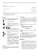
ENH003-12 5. We Makita Corporation as the responsible manufacturer declare that the following Makita machine(s): Designation of Machine: Slide Compound Miter Saw 6. For European countries only EC Declaration of Conformity 7. Model No.
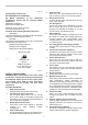
18. 19. 20. 21. 22. 7. Use outdoor extension leads. When tool is used outdoors, use only extension cords intended for outdoor use. Stay alert. Watch what you are doing. Use common sense. Do not operate tool when you are tired. Check damaged parts. Before further use of the tool, a guard or other part that is damaged should be carefully checked to determine that it will operate properly and perform its intended function.
27. 28. 29. 30. 31. 32. 33. 34. 35. 36. 37. 38. 39. 40. Do not use the saw to cut other than wood, aluminum or similar materials. Connect miter saws to a dust collecting device when sawing. Select saw blades in relation to the material to be cut. Take care when slotting. Replace the kerf board when worn. Do not use saw blades manufactured from high speed steel. Some dust created from operation contains chemicals known to cause cancer, birth defects or other reproductive harm.
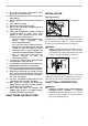
Blade guard 1. Blade guard 1. Blade guard 1 1 009486 With the blade guard so positioned, cleaning can be more completely and efficiently accomplished. When cleaning is complete reverse procedure above and secure bolt. Do not remove spring holding blade guard. If guard becomes damaged through age or UV light exposure, contact a Makita service center for a new guard. DO NOT DEFEAT OR REMOVE GUARD. 009485 When lowering the handle, the blade guard rises automatically.
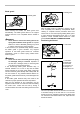
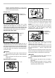
1. Lock lever 2. Locking screw 1 2 3 1 4 009496 First, unplug the tool. Loosen all the screws (3 each on left and right) securing the kerf boards. Re-tighten them only to the extent that the kerf boards can still be easily moved by hand. Lower the handle fully and push in the stopper pin to lock the handle in the lowered position. Loosen the locking screw counterclockwise which secures the upper slide poles and also push forward the lock lever which secures the lower slide poles.
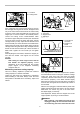
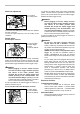
handle is lowered completely. If a blade makes contact with the base it may cause kickback and result in serious personal injury. 1. Latch lever 1 Stopper arm 1. Stopper arm 2. Adjusting screw 2 1 010322 To adjust the bevel angle, loosen the lever at the rear of the tool counterclockwise. Push the latch lever forward as shown in the figure fully while supporting the weight of the saw head so as to release the pressure on the lock pin.
To prevent the switch trigger from being accidentally pulled, a lock-off button is provided. To start the tool, press in the lock-off button and pull the switch trigger. Release the switch trigger to stop. Slide lock adjustment 1. Lock lever 2. Locking screw WARNING: Before plugging in the tool, always check to see that the switch trigger actuates properly and returns to the "OFF" position when released. Do not pull the switch trigger hard without pressing in the lock-off button.
Aligning the laser line Laser beam action For models LS1216L only A B 1. Switch for laser 1 009494 Laser line can be shifted to either the left or right side of the blade according to the applications of cutting. Refer to explanation titled "Laser beam action" regarding its shifting method. 009492 CAUTION: Never look into the laser beam. Direct laser beam may injure your eyes. • LASER RADIATION, DO NOT STARE INTO THE BEAM OR VIEW DIRECTLY WITH OPTICAL INSTRUMENTS, CLASS 2M LASER PRODUCT.
Installing or removing saw blade • • WARNING: Always be sure that the tool is switched off and unplugged before installing or removing the blade. Accidental start up of the tool may result in serious personal injury. Use only the Makita socket wrench provided to install or remove the blade.Failure to use the wrench may result in overtightening or insufficient tightening of the hex bolt and serious personal injury. 1. Shaft lock 2. Blade case 3. Hex bolt 1 2 1.
movement and severe vibration resulting in possible loss of control during operation and in serious personal injury. To install the blade, mount it carefully onto the spindle, making sure that the direction of the arrow on the surface of the blade matches the direction of the arrow on the blade case. Dust box (Optional accessory) 1. Dust box 2. Cover 3. Button 1 1. Hex bolt 3 2 006793 Insert the dust box into the dust nozzle. Empty the dust box when necessary.
of a coasting blade may result in serious personal injury and damage to the workpiece. When cutting a workpiece that is longer than the support base of the saw, the material should be supported the entire length beyond the support base and at the same height to keep the material level. Proper workpiece support will help avoid blade pinch and possible kickback which may result in serious personal injury. Do not rely solely on the vertical vise and/or horizontal vise to secure the workpiece.
Position the vise arm according to the thickness and shape of the workpiece and secure the vise arm by tightening the screw. If the screw to secure the vise arm contacts the carriage, install the screw on the opposite side of vise arm. Make sure that no part of the tool contacts the vise when lowering the handle fully and pulling or pushing the carriage all the way. If some part contacts the vise, re-position the vise. Press the workpiece flat against the guide fence and the turn base.
mark (saw mark) in the workpiece and the precision of the cut will be impaired. During a slide cut, gently push the carriage toward the guide fence without stopping. If the carriage movement is stopped during the cut, a mark will be left in the workpiece and the precision of the cut will be impaired. • • 2. 1. Lock lever 2. Locking screw 2 WARNING: Make sure the blade is not contacting the workpiece, etc. before the switch is turned on.
kickback resulting in possible in serious personal injury. 3. NOTICE: • When pressing down the handle, apply pressure in parallel with the blade. If a force is applied perpendicularly to the turn base or if the pressure direction is changed during a cut, the precision of the cut will be impaired. • Before bevel-cutting, an adjustment of the upper fence and lower fence maybe required. Refer to the section titled "Guide fence adjustment".
1 (2) (1) (2) (1) (3) (2) (1) (1) (2) (4) with its CEILING CONTACT EDGE against the guide fence on the saw. • The finished piece to be used will always be on the LEFT side of the blade after the cut has been made. In the case of right bevel cut 1. Inside corner 2. Outside corner 2 (1) (2) Table (A) Bevel angle Molding position in 52/38° type 45° type Fig. A 001557 For inside corner Measuring Measure the wall length and adjust workpiece on table to cut wall contact edge to desired length.
1 7. 1. Crown molding stopper L (Optional accessory) 2. Crown molding stopper R (Optional accessory) 3. Turn base 2 3 Cutting aluminum extrusion 1. Guide fence 2. Vise 3. Spacer block 4. Aluminum extrusion 5. Spacer block 1 2 3 4 5 009521 009523 1. Crown molding stopper L 2. Crown molding stopper R 3. Turn base 3 When securing aluminum extrusions, use spacer blocks or pieces of scrap as shown in the figure to prevent deformation of the aluminum.
Example: When cutting workpieces 115 mm and 120 mm high, use a wood facing with the following thickness. Miter angle 0° Left and Right 45° Left and Right 52° Right 60° results and kickback which may result in serious personal injury Be sure to return the stopper arm to the original position when performing other than groove cutting. Attempting to make cuts with the stopper arm in the incorrect position could lead to unexpected cutting results and kickback which may result in serious personal injury.
move resulting in possible loss of control, kickback and serious personal injury. 1 2 3 4 1. Upper fence 2. Vertical vise 3. Workpiece 4. Platform 4 010356 3 1 (6) 2 (7) 1. Screws (two each side) 2. Lower fence 3. Base 4. Platform (8) 010357 NOTE: • The maximum cutting capacity in height will be reduced by the same amount as the platform thickness. (4) Place the platform on the tool so that it extends equally over each side of the tool base.
the carriage. Turn the grip counterclockwise which secures the turn base. Turn the turn base so that the pointer points to 0° on the miter scale. Then turn the turn base slightly clockwise and counterclockwise to seat the turn base in the 0° miter notch. (Leave as it is if the pointer does not point to 0°.) Loosen the hex sockets bolts securing the guide fence using the socket wrench. 009506 1.
Push the carriage toward the guide fence and tighten the locking screw clockwise and pull the lock lever towards the front of the saw to secure the carriage. Lower the handle fully and lock it in the lowered position by pushing in the stopper pin. Loosen the lever at the rear of the tool. 3 2 (2) 2 1. 0 ゚ Angle adjusting bolt 2. Lever 3. Latch lever 3 4 009608 Adjust the 45° bevel angle only after performing 0° bevel angle adjustment.
changed by turning two screws with a hex wrench. (The movable range of laser line is factory adjusted within 1 mm from the side surface of blade.) To shift the laser line movable range further away from the side surface of blade, turn the two screws counterclockwise after loosening the adjusting screw. Turn these two screws clockwise to shift it closer to the side surface of the blade after loosening the adjusting screw.
NOTE: • If the lens does not come out, loosen the screw further and pull out the lens again without removing the screw. ACCESSORIES WARNING: These Makita accessories or attachments are recommended for use with your Makita tool spcified in this manual. The use of any other accessories or attachments may result in serious personal injury. • Only use the Makita accessory or attachment for its stated purpose. Misuse of an accessory or attachment may result in serious personal injury.
Makita Corporation Anjo, Aichi, Japan 884908A220 28