www.makitatools.com NOTICE Carefully read this instruction manual and the engine manual before attempting to operate this compressor. WARNING: This product contains chemicals known to the State of California to cause cancer, and birth defects or other reproductive harm. Wash hands after handling this product.
OWNERS MANUAL FOR Gas Compressor MODEL No. MAC5501G SPECIFICATION CHART Maximum Horsepower SCFM @ 40 PSIG SCFM @ 100 PSIG Cut-In Pressure Cut-Out Pressure Engine RPM Tank Size Weight 5.5 HP 14 12.5 110 135 3600 10 Gallon 190 lbs. IMPORTANT - Read the Safety Guidelines and ALL instructions carefully before operating. Wear hearing protection Wear eye protection www.makitatools.
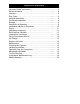
TABLE OF CONTENTS Important Safety Instructions …………………………………. …….…..4 Emissions Notice ………………………………………………. ………...8 Glossary ………………………………………………………… ………...8 Duty Cycle ……………………………………………………… ………...9 General Information ……………………………………………. ………...9 On-Receipt Inspection …………………………………………. ………...9 Storage …………………………………………………………. ………...9 Description of Operation ………………………………………. ………...9 Installation & Break In Procedure …………………………….. ……….10 Piping …………………………………………………………… ……….11 Operating Procedures …………………………………..
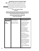
IMPORTANT SAFETY INSTRUCTIONS DANGER: Carbon Monoxide. Using an engine indoors can kill you in minutes. Engine exhaust contains high levels of carbon monoxide (CO), a poisonous gas you cannot see or smell. You may be breathing CO even if you DO NOT smell engine exhaust. The engine exhaust from this product contains chemicals known to the State of California to cause cancer, birth defects, or other reproductive harm.
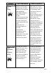
HAZARD Risk of Air Tank Bursting Risk of Attachments and Accessories Bursting WHAT CAN HAPPEN The following conditions could lead to a weakening of the tank and RESULT IN A VIOLENT TANK EXPLOSION RESULTING IN SERIOUS INJURY TO YOU OR OTHERS: · Failure to properly drain condensed water from the tank, causing rust and thinning of the tank wall. · Modifications or attempted repairs to the tank.
HAZARD Risk From Noise Risk of Explosion or Fire Risk to Breathing Page 6 WHAT CAN HAPPEN Under some conditions and duration of use, noise from this product may contribute to hearing loss. Never operate the compressor in an atmosphere where flammable vapors are present. Doing so can result in serious injury to you or others. · The compressed air from your compressor is not safe for breathing. The air stream may contain carbon monoxide or other vapors, or particles from the tank or other components.
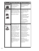
HAZARD Risk from Compressed Air Risk from Moving Parts Risk of Burn Risk of Injury from Lifting WHAT CAN HAPPEN The compressed air stream can cause soft tissue damage, and can propel dirt, chips, loose particles and small objects at high speed, resulting in property damage or personal injury. If your attempt repair or maintenance while the compressor is operating, you can expose yourself to moving parts. These moving parts can cause serious injury.
This product may not be equipped with a sparkarresting muffler. If the product is not equipped and will be used around flammable materials or on land covered with materials such as agricultural crops, forest, brush, grass, or other similar items, then an approved spark arrester must be installed and is legally required in the state of California.
GLOSSARY (con't.) where applicable. CUT-OUT PRESSURE: When you start your air compressor, it begins to run, air pressure in the tank begins to build. It builds to a certain pressure before the engine automatically idles down - protecting your air tank from pressure higher than its design rating. The pressure at which the engine idles down is called "cut-out pressure". DUTY CYCLE All Makita manufactured air compressors are recommended to be operated on not more than a 50% duty cycle.
DESCRIPTION OF OPERATION (con't) AIR INTAKE FILTER: This filter is designed to clean air coming into the compressor pump. This filter must always be clean and free from obstructions. See "Maintenance". AIR COMPRESSOR PUMP: To compress air, the pistons move up and down in the cylinder. On the down stroke, air is drawn in through the air intake valve. The exhaust valve remains closed. On the upstroke of the piston, air is compressed.
INSTALLATION AND BREAK-IN PROCEDURES (con't.) Initial Start Up Procedure: 1. Check engine & pump oil. 2. Open the air receiver's drain valve. 3. Run the compressor for a minimum of of twenty (20) minutes in the no-load condition to seat the piston ring. 4. Close air receiver drain valve. Your compressor is now ready for use. Piping Plastic or PVC pipe is not designed for use with compressed air. Regardless of its indicated pressure rating, plastic pipe can burst from air pressure.
OPERATING PROCEDURES FILLING THE COMPRESSOR WITH OIL BEFORE OPERATING THE AIR COMPRESSOR 1) Remove the oil filler plug PLEASE CHECK THE FOLLOWING CAREFULLY: 1) Check to see that nuts and bolts are all snug. 2) Check if the quantity and quality of oil is correct. 3) If the intake filters are dirty, they should be replaced or cleaned.
OPERATING PROCEDURES CHECKING BELT TENSION Adjust belt(s) so when pressure is applied at the center, there is approximately 1/2" slack (see diagram "Figure A" below). If the belt is installed too tight, the engine might be overloaded. This will cause the engine to overheat. If the belt is installed too loosely, it will slip and excessive wear and vibration will occur. HOW TO INSTALL A NEW BELT IF REQUIRED: 1) Turn off engine. Wait until engine is completely stopped. 2) Remove belt guard.
EXTRA CARE SHOULD BE TAKEN TO AVOID PERSONAL INJURIES WITH AUTOMATICALLY CONTROLLED COMPRESSORS MAINTENANCE SCHEDULE DAILY OR BEFORE EACH USE 1) Check oil level 2) Drain condensation from air receiver 3) Check for any unusual noise or vibration 4) Be sure all nuts and bolts are tight WEEKLY 1) Turn off engine. Clean dust and foreign matter from cylinder head, engine, fan blades, intercooler, and air receiver.
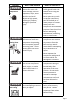
TROUBLE SHOOTING PROBLEM POSSIBLE CAUSE Will not start Low pressure Oil in Discharge Compressor Overheats Compressor loads & unloads or idols up & down excessively Safety valve leaks Drain cock open Loose tubes or fittings Dirty or plugged air filter Defective unloader valve Too much oil in the crankcase Improper oil viscosity Compressor overheated Restricted air filter Worn piston rings Dirty compressor head, cylinder or intercooler Clogged inlet filter Operating pressure too high Low oil or wrong o
TROUBLE SHOOTING PROBLEM POSSIBLE CAUSE CORRECTIVE ACTION Insufficient output, low discharge pressure Clogged inlet filter Leaks in air lines, air valves, fittings, etc. Drive belts slipping.
TROUBLE SHOOTING PROBLEM POSSIBLE CAUSE System pressure leaking back through check valve when compressor is stopped.
TROUBLE SHOOTING PROBLEM Piston rings not seated POSSIBLE CAUSE CORRECTIVE ACTION Compressor operating outside in cold conditions or inlet filter not protected against weather Worn piston rings Piston rings not seated Provide adequate protection against extreme weather conditions. Replace piston rings See below. Allow 100 hours of normal operation for new rings to seat.
COMPRESSOR MAINTENANCE LOG DATE TYPE OF MAINTENANCE OR REPAIRS Page 19
Page 20
INSTRUCTION MANUAL MANUEL D'INSTRUCTION MANUAL DE INSTRUCCIONES Pneumatic Brad Nailer Cloueur Pneumatique Polyvalent Clavadora Neumática para Clavos de Cabeza Redonda AF505N 014916 IMPORTANT: Read Before Using. IMPORTANT: Lire avant usage. IMPORTANTE: Leer antes de usar.
ENGLISH (Original instructions) SPECIFICATIONS Model AF505N Air pressure 4.0 - 8.0 kgf/cm2G (60 - 115 PSIG) Nail length 15 mm (5/8") - 50 mm (2") Nail capacity 100 pcs. Min. hose diameter 6.5 mm (1/4") Dimensions (L X H X W) 260 mm X 237 mm X 64 mm (10-1/4" X 9-5/8" X 2-1/2") Net weight 1.4 kg (3.01 lbs) • Due to our continuing program of research and development, the specifications herein are subject to change without notice. • Note: Specifications may differ from country to country.
26. 13. Never use the tool with other than compressed air. If bottled gas (carbon dioxide, oxygen, nitrogen, hydrogen, air, etc.) or combustible gas (hydrogen, propane, acetylene, etc.) is used as a power source for this tool, the tool will explode and cause serious injury. 14. Always check the tool for its overall condition and loose screws before operation. Tighten as required. 15. Make sure all safety systems are in working order before operation.
INSTALLATION • Selecting compressor Compressor air output per minute CFM Lubrication (ft3 /min) 3 ) IG PS 115 G( G) PSI cm gf/ 100 k 2 G( 0 8. cm kgf/ SIG) 7.0 (85P 2 m G c f/ g 6.0k 2 2 1 0 CAUTION: Low air output of the compressor, or a long or smaller diameter air hose in relation to the nailing frequency may cause a decrease in the driving capability of the tool.
FUNCTIONAL DESCRIPTION • ASSEMBLY CAUTION: Always disconnect the hose before adjusting or checking function on the tool. • • Adjusting depth of nailing 1. Adjuster A B CAUTION: Always disconnect the hose before carrying out any work on the tool. Load the same kind, size and uniform length of nails when loading nails in the magazine. Loading nailer 1 007181 To adjust the depth of nailing, turn the adjuster.
The direction of exhaust air can be changed 360 degrees of angle by turning the exhaust cover with a hand. Connecting air hose 2 1 1. Air fitting 2. Air socket Removing nails • CAUTION: Do not use deformed nails or nail strip. Failure to do so causes poor nail feeding. WARNING: Always disconnect the hose before removing nails. Open the slide door and remove nails from the magazine. • 007187 Slip the air socket of the air hose onto the air fitting on the nailer.
Nails Nail 014925 When the tool is not to be used for an extended period of time, lubricate the tool using pneumatic tool oil and store the tool in a safe place. Avoid exposure to direct sunlight and/or humid or hot environment. 004310 Handle nail coils and their box carefully. If the nail coils have been handled roughly, they may be out of shape or their connector breaks, causing poor nail feed. Avoid storing nails in a very humid or hot place or place exposed to direct sunlight.
After operation, always drain the compressor tank and the air filter. If moisture is allowed to enter the tool, It may result in poor performance and possible tool failure. Check regularly to see if there is sufficient pneumatic oil in the oiler of the air set. Failure to maintain sufficient lubrication will cause O-rings to wear quickly. NOTE: • Some items in the list may be included in the tool package as standard accessories. They may differ from country to country. 1. Oiler 2.
FRANÇAIS (Mode d’emploi original) SPÉCIFICATIONS Modèle AF505N Pression d'air 4,0 - 8,0 kgf/cm2G (60 - 115 PSI) Longueur de clou 15 mm (5/8") - 50 mm (2") Capacité de clouage 100 unités Diamètre min.
10. 11. 12. 13. 14. 15. 16. 17. 18. 19. Il se peut que des réglementations locales s'appliquent concernant les niveaux de bruit permis. Veuillez les respecter. Le cas échéant, des volets doivent être installés pour réduire le bruit. Ne modifiez pas l'élément de contact. Il permet de prévenir toute décharge accidentelle et doit donc être laissé en place. Il est également très dangereux de fixer la gâchette en position de marche. Il ne faut jamais essayer d'immobiliser la gâchette.
30. 31. 32. 33. 34. INSTALLATION Sélection du compresseur Sortie d'air du compresseur par minute 29. (3) Avant de réparer un blocage. (4) Avant de déplacer l'outil vers un autre lieu. Procédez au nettoyage et à l'entretien de l'outil une fois le travail terminé. Maintenez l'outil en excellente condition. Lubrifiez les pièces mobiles pour éviter qu'elles ne rouillent et pour limiter l'usure entraînée par la friction. Retirez toute poussière déposée sur les pièces.
• ATTENTION: La capacité d'entraînement de l'outil risque de diminuer si la sortie d'air du compresseur est faible ou si le tuyau d'air est trop long ou d'un diamètre trop petit pour la fréquence de clouage. DESCRIPTION DU FONCTIONNEMENT Lubrification • ATTENTION: Débranchez toujours le tuyau avant de régler ou de vérifier le fonctionnement de l'outil. Réglage de la profondeur de clouage 1.
Raccordement du tuyau d'air ASSEMBLAGE • • 2 1 ATTENTION: Débranchez toujours le tuyau avant tout réglage de l'outil. Chargez des clous de même type, de même taille et de même longueur dans le magasin. 1. Raccord à air 2. Douille à air Chargement de la cloueuse 007187 Glissez la douille à air du tuyau d'air dans le raccord à air de la cloueuse. Assurez-vous que la douille à air est verrouillée fermement en position lorsque vous installez le raccord à air.
Clous Retrait des clous • ATTENTION: N'utilisez pas des clous déformés ou en bande, car l'alimentation fera défaut. Clou AVERTISSEMENT: Déconnectez toujours le tuyau avant de retirer les clous. Ouvrez la porte coulissante et retirez les clous du magasin. • 004310 Manipulez avec soin les bandes de clous et les boîtes de clous.
Avec l'outil débranché, inspectez-le quotidiennement pour vous assurer que l'élément de contact et la gâchette se déplacent librement. N'utilisez pas l'outil si l'élément de contact ou la gâchette se coince. 1. Filtre à air 1 004318 Après l'utilisation, videz toujours le réservoir du compresseur et le filtre à air. L'outil risque de mal fonctionner ou de tomber en panne si l'humidité y pénètre.
ACCESSOIRES EN OPTION ATTENTION: Ces accessoires ou pièces complémentaires sont recommandés pour l'utilisation avec l'outil Makita spécifié dans ce mode d'emploi. L'utilisation de tout autre accessoire ou pièce complémentaire peut comporter un risque de blessure. N'utilisez les accessoires ou pièces qu'aux fins auxquelles ils ont été conçus. Si vous désirez obtenir plus de détails concernant ces accessoires, veuillez contacter le centre de service après-vente Makita le plus près.
ESPAÑOL (Instrucciones originales) ESPECIFICACIONES Modelo AF505N Presión de aire 4,0 - 8,0 kgf/cm2G (60 - 115 PSIG) Longitud del clavo 15 mm (5/8") - 50 mm (2") Capacidad de clavos 100 pzs Diámetro mínimo de la manguera 6,5 mm (1/4") Dimensiones (La x Al x An) 260 mm X 237 mm X 64 mm (10-1/4" X 9-5/8" X 2-1/2") Peso neto 1,4 kg (3,01 lbs) • Debido a nuestro programa continuo de investigación y desarrollo, las especificaciones aquí dadas están sujetas a cambios sin previo aviso.
10. 11. 12. 13. 14. 15. 16. 17. 18. Puede que haya regulaciones locales respecto al ruido las cuales deben cumplirse al mantener los niveles de ruido dentro de los límites preestablecidos. En determinados casos, deberán usarse silenciadorespara contener el ruido. No juegue con el elemento de contacto: esto evita la descarga accidental, por lo que debe conservarse y no quitarse. Asegurar el gatillo en la posición de encendido "ON" también es muy peligroso. Nunca intente trabar el gatillo.
(2) 30. 31. 32. 33. 34. INSTALACIÓN Cómo elegir un compresor Salida de aire del compresor por minuto 29. Antes de realizar cualquier mantenimiento o reparación. (3) Antes de liberar algún atoramiento. (4) Antes de llevar la herramienta a una locación distinta. Realice operaciones de limpieza y mantenimiento justo después de haber terminado la labor. Mantenga la herramienta en excelentes condiciones. Lubrique las piezas móviles para prevenir la oxidación y minimizar el desgaste por fricción.
suministro de aire deberán tener una escala de presión de funcionamiento mínima de 10,7 kgf/cm2G (150 PSIG) o de 150 por ciento de la máxima presión producida en el sistema, cualquiera sea la mayor. • DESCRIPCIÓN DEL FUNCIONAMIENTO PRECAUCIÓN: Una baja presión en la salida de aire del compresor o una manguera de aire de mayor o menor diámetro en relación con la frecuencia de clavado puede causar una disminución en la capacidad de manejo de la herramienta.
PRECAUCIÓN: Siempre desconecte la manguera antes de instalar el adaptador de nariz. Para prevenir que la superficie de la pieza de trabajo se raye o dañe, use un adaptador de nariz. ENSAMBLE • • • PRECAUCIÓN: Siempre desconecte la manguera antes de llevar a cabo cualquier servicio de mantenimiento en la herramienta. Recargue el cartucho de almacenamiento con clavos de un mismo tipo, tamaño y longitud uniforme. Cómo conectar la manguera 1 Cómo cargar una clavadora 2 1.
Dirección del aire de escape 1 1. Superficie de contacto 2. Brazo de contacto 1 1. Cubierta de escape 2 014924 Clavos 007189 La dirección del aire de escape puede modificarse a un ángulo de 360 grados al girar la cubierta de escape con la mano. Clavo Extracción de clavos • PRECAUCIÓN: No utilice clavos deformes, ni una tira de clavos con clavos deformes. No seguir esta indicación provocaría una alimentación de clavos deficiente.
Mantenimiento del compresor, juego de aire o manguera de aire 1. Llave de drenaje 1 007192 Con la herramienta desconectada, realice una inspección diaria para garantizar un movimiento libre del elemento de contacto y el gatillo. No use la herramienta si el elemento de contacto o el gatillo quedan trabados o atorados. 004317 1. Filtro de aire 1 004318 Luego de utilizarla, vacíe siempre el tanque del compresor y el filtro de aire.
Horno Diluyente 004320 Para mantener la SEGURIDAD y FIABILIDAD del producto, las reparaciones, y cualquier otra tarea de mantenimiento o ajuste deberán ser realizadas en Centros de Servicio Autorizados por Makita, empleando siempre repuestos Makita. ACCESORIOS OPCIONALES PRECAUCIÓN: Estos accesorios o aditamentos (incluidos o no) están recomendados para utilizar con su herramienta Makita especificada en este manual.
25
26
27
< USA only > WARNING Some dust created by power sanding, sawing, grinding, drilling, and other construction activities contains chemicals known to the State of California to cause cancer, birth defects or other reproductive harm. Some examples of these chemicals are: • lead from lead-based paints, • crystalline silica from bricks and cement and other masonry products, and • arsenic and chromium from chemically-treated lumber.
Embedded Secure Document The file http://cdn.makita.com/apps/cms/doc/prod/AN9/012c7d28-9b7e-435f-8a61159cca5c19e4_AN923_IM.pdf is a secure document that has been embedded in this document. Double click the pushpin to view. http://cdn.makita.com/apps/cms/doc/prod/AN9/012c7d28-9b7e-435f-8a61-159cca5c19e4_AN923_IM.