Router MODEL RP1100/RP1101 003650 I N S T R U C T I O N M A N U A L WARNING: For your personal safety, READ and UNDERSTAND before using. SAVE THESE INSTRUCTIONS FOR FUTURE REFERENCE. w w w. m a k i t a t o o l s.
SPECIFICATIONS Model RP1100 Collet chuck capacity No load speed (RPM) RP1101 1/2” and 1/4” 24,000/min. 8,000 - 24,000/min. Overall length 291 mm (11-1/2”) Net weight 4.2 kg (9.3 lbs) • Manufacturer reserves the right to change specifications without notice. • Specifications may differ from country to country. GENERAL SAFETY RULES USA001-2 (For All Tools) WARNING: Read and understand all instructions.
5. Avoid body contact with grounded surfaces such as pipes, radiators, ranges and refrigerators. There is an increased risk of electric shock if your body is grounded. 6. Do not expose power tools to rain or wet conditions. Water entering a power tool will increase the risk of electric shock. 7. Do not abuse the cord. Never use the cord to carry the tools or pull the plug from an outlet. Keep cord away from heat, oil, sharp edges or moving parts. Replace damaged cords immediately.
SERVICE 23. Tool service must be performed only by qualified repair personnel. Service or maintenance performed by unqualified personnel could result in a risk of injury. 24. When servicing a tool, use only identical replacement parts. Follow instructions in the Maintenance section of this manual. Use of unauthorized parts or failure to follow Maintenance instructions may create a risk of electric shock or injury.
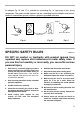
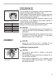
An adapter Fig. “B” and “C” is available for connecting Fig. “A” type plugs to two- prong receptacles. The green-colored rigid ear, lug, etc., extending from the adapter must be connected to a permanent ground, such as a properly grounded outlet box. Adapter Grounding Means Cover of Grounded Outlet Box Grounding Blade Fig. A Fig. B SPECIFIC SAFETY RULES Fig. C USB013-3 DO NOT let comfort or familiarity with product (gained from repeated use) replace strict adherence to router safety rules.
13. Do not touch the bit immediately after operation; it may be extremely hot and could burn your skin. 16. Draw attention to the need to use cutters of the correct shank diameter and suitable for the speed of the tool. 14. Always lead the power supply cord away from the tool towards the rear. 17. Some material contains chemicals which may be toxic. Take caution to prevent dust inhalation and skin contact. Follow material supplier safety data. 15.
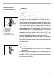
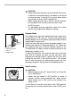
FUNCTIONAL DESCRIPTION • 003654 2 3 4 1. 2. 3. 4. 5. 6. 7. 1 7 5 6 Lock lever Adjusting knob Depth pointer Fast-feed button Stopper pole Fast-feed button Stopper pole setting nut 003656 Adjusting the depth of cut Place the tool on a flat surface. Press the lock lever down and lower the tool body until the bit just touches the flat surface. Release the lock lever to hold the tool body down. Turn the stopper pole setting nut counterclockwise to loosen.
• 003658 1 3 4 2 1. 2. 3. 4. Stopper pole Adjusting hex bolt Hex nut Stopper block 003662 CAUTION: Since excessive cutting may cause overload of the motor or difficulty in controlling the tool, the depth of cut should not be more than 15 mm (9/16”) at a pass when cutting grooves with an 8 mm (5/16”) diameter bit. • When cutting grooves with a 20 mm (13/16”) diameter bit, the depth of cut should not be more than 5 mm (3/16”) at a pass.
Speed adjusting dial 003666 1 1. Speed adjusting dial Number 1 2 3 4 5 6 RPM 8,000 10,000 14,000 18,000 22,000 24,000 For model RP1101 only The tool speed can be changed by turning the speed adjusting dial to a given number setting from 1 to 6. Higher speed is obtained when the dial is turned in the direction of number 6. And lower speed is obtained when it is turned in the direction of number 1. This allows the ideal speed to be selected for optimum material processing, i.e.
Insert the bit all the way into the collet chuck and withdraw it very slightly ( approx. 2mm;1/16” ). Then tighten the collet chuck securely with the two wrenches. These routers accommodate the bits with 1/2” diameter shank. When using the 1/4” diameter shank bit, replace the equipped collet chuck with the one for 1/4” diameter shank bit which is provided as the standard accessory. To remove the bit, follow the installation procedure in reverse.
• 003679 1 2 When using the straight guide, be sure to install it on the right side in the feed direction. This will help to keep it flush with the side of the workpiece. Straight guide (optional accessory) The straight guide is effectively used for straight cuts when chamfering or grooving. To install the straight guide, insert the guide bars into the holes in the tool base. Adjust the distance between the bit and the straight guide.
003799 1 To install the templet guide, insert the templet guide in center hole in the base plate and secure in place with the lock nut. 4 2 3 1. 2. 3. 4. Lock nut Templet guide Router bit Base plate 003696 6 1 Secure the templet to the workpiece. Place the tool on the templet and move the tool with the templet guide sliding along the side of the templet. 2 3 4 1. 2. 3. 4. 5. 6. 5 Router bit Base Templet Workpiece Templet guide Lock nut MAINTENANCE • 001145 1 1.
003704 1 2 Use a screwdriver to remove the brush holder caps. Take out the worn carbon brushes, insert the new ones and secure the brush holder caps. To maintain product SAFETY and RELIABILITY, repairs, any other maintenance or adjustment should be performed by Makita Authorized or Factory Service Centers, always using Makita replacement parts. 1. Brush holder cap 2.
Memo 14
Memo 15
Memo 16
Cut First-Class Postage Required Post Office will not deliver without proper postage. Makita U.S.A., Inc.
MAIL THIS PORTION Your answers to the following questions are appreciated. 1. This product was purchased from: Home Center 3. How did you learn about this product: Magazine Radio Hardware/Lumber Store From Dealer Exhibition Tool Distributor Newspaper From Friend Industrial Supply Store Display Previous Usage Construction Supply Catalog Other ( Other ( ) 2. Use of the product is intended for: ) 4.
FACTORY SERVICE CENTERS 1-800-4-MAKITA RETAIN THIS PORTION FOR YOUR RECORDS ARIZONA 3707 E. Broadway Rd., Ste. 6 Phoenix, AZ 85040 (602) 437-2850 FLORIDA 750 East Sample Road Pompano Beach, FL 33064 (954) 781-6333 MISSOURI 9876 Watson Road St. Louis, MO 63126-2221 (314) 909-9889 PENNSYLVANIA 1704 Babcock Blvd. Pittsburgh, PA 15209 (412) 822-7370 CALIFORNIA 41850 Christy St. Fremont, CA 94538-5107 (510) 657-9881 GEORGIA 4680 River Green Parkway NW Duluth, GA 30096 (770) 476-8911 NEBRASKA 4129 S.
WARNING Some dust created by power sanding, sawing, grinding, drilling, and other construction activities contains chemicals known to the State of California to cause cancer, birth defects or other reproductive harm. Some examples of these chemicals are: • lead from lead-based paints, • crystalline silica from bricks and cement and other masonry products, and • arsenic and chromium from chemically-treated lumber. Your risk from these exposures varies, depending on how often you do this type of work.