ENGLISH (Original instructions) INSTRUCTION MANUAL Cordless Hedge Trimmer BUH550 BUH650 UH550D UH650D 011146 IMPORTANT: Read Before Using.
ENGLISH (Original instructions) SPECIFICATIONS Model BUH550 Blade length Strokes per minute (min-1) Overall length UH550D BUH650 550 mm 1,000 - 1,800 1,070 mm UH650D 650 mm 1,074 mm 1,000 - 1,800 1,150 mm 1,154 mm Net weight 5.1 kg 5.2 kg Rated voltage D.C.36V D.C.36V • Due to our continuing programme of research and development, the specifications herein are subject to change without notice. • Specifications and battery cartridge may differ from country to country.
ENH032-2 GEA006-2 For European countries only General Power Tool Safety Warnings EC Declaration of Conformity We Makita Corporation as the responsible manufacturer declare that the following Makita machine(s): Designation of Machine: Cordless Hedge Trimmer Model No./ Type: BUH550,UH550D,BUH650,UH650D Specifications: see "SPECIFICATIONS" table.
dangerous in the hands of untrained users. Maintain power tools. Check for misalignment or binding of moving parts, breakage of parts and any other condition that may affect the power tool’s operation. If damaged, have the power tool repaired before use. Many accidents are caused by poorly maintained power tools. 22. Keep cutting tools sharp and clean. Properly maintained cutting tools with sharp cutting edges are less likely to bind and are easier to control. 23.
GEB062-3 CORDLESS HEDGE TRIMMER SAFETY WARNINGS 1. 2. 3. 4. 5. 6. 7. 8. 9. 10. 11. 12. 13. 14. 15. Hold the power tool by insulated gripping surfaces only, because the cutter blade may contact hidden wiring. Cutter blades contacting a "live" wire may make exposed metal parts of the power tool "live" and could give the operator an electric shock. Keep all parts of the body away from the cutter blade. Do not remove cut material or hold material to be cut when blades are moving.
3. 4. 5. 6. 7. 8. 9. If operating time has become excessively shorter, stop operating immediately. It may result in a risk of overheating, possible burns and even an explosion. If electrolyte gets into your eyes, rinse them out with clear water and seek medical attention right away. It may result in loss of your eyesight. Do not short the battery cartridge: (1) Do not touch the terminals with any conductive material.
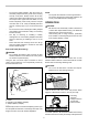
Handle mounting positions Speed change 2 1 1 3 1. Adjusting dial 011233 The strokes per minute can be adjusted just by turning the adjusting dial. This can be done even while the tool is running. The dial is marked 1 (lowest speed) to 6 (full speed). Refer to the table below for the relationship between the number settings on the adjusting dial and the strokes per minute. 1. Housing 2. Knob 3.
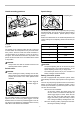
Battery remaining capacity indicator (only for models with Battery BL3622A) ASSEMBLY Battery BL3622A is equipped with the battery remaining capacity indicator. • 1. Indicator lamps 2. CHECK button 1 CAUTION: Always be sure that the tool is switched off and the battery cartridge is removed before carrying out any work on the tool. Battery adapter (Accessory) 2 1 2 011715 Press the CHECK button to indicate the battery remaining capacity. The indicator lamps will then light for approx. three seconds.
• • • • To insert the battery adapter, align the tongue on the battery adapter with the groove in the housing and slip it into place. Always insert it all the way until it locks in place with a little click. If you can see the red part on the upper side of the button, it is not locked completely. Insert it fully until the red part cannot be seen. If not, it may accidentally fall out of the tool, causing injury to you or someone around you. Do not use force when inserting the battery adapter.
of 3 - 4 seconds per meter. 1 Installing or removing chip receiver (accessory) 1. String • CAUTION: Always be sure that the tool is switched off and the battery cartridge is removed before installing or removing chip receiver. NOTE: • When replacing the chip receiver, always wear gloves so that hands and face does not directly contact the blade. Failure to do so may cause personal injury. • Always be sure to remove the blade cover before installing the chip receiver.
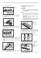
Removing or installing shear blade 1. Press the hooks on both sides 2. Unlock the hooks • 1 2 • 009293 • CAUTION: The blade cover (standard equipment) cannot be installed on the tool with the chip receiver being installed. Before carrying or storing, uninstall the chip receiver and then install the blade cover to avoid blade exposure. CAUTION: Before removing or installing shear blade, always be sure that the tool is switched off and the battery cartridge is removed.
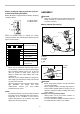
Set the crank at the angle as shown in the figure with a slotted bit screwdriver. 1 1. Oval hole of shear blade 1. Crank 1 011259 Take out the blade cover from the old shear blades and fit it onto the new ones for easy handling during the replacement of blades. 011256 Remove two screws from the shear blades and the shear blade unit will be taken out. 1 1. Screws 2. Shear blade 2 009302 Place the new shear blades on the tool so that the oval holes in the shear blades fit onto the crank.
Reinstall the holder cap cover on the tool. Install the plate, under cover on the tool. Tighten the screw firmly. Storage The hook hole in the bottom of the blade cover is convenient for hanging the tool from a nail or screw on the wall. NOTE: • There is no distinction between the top and bottom of the plate. Remove the blade cover and then turn on the tool to check it for proper movement. NOTE: • When the shear blades does not operate properly, there is a poor fit between the blades and crank.
NOTE: • Some items in the list may be included in the tool package as standard accessories. They may differ from country to country.
Makita Corporation Anjo, Aichi, Japan 884974C227 16 www.makita.