
Instructions / Assembly


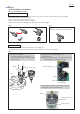


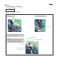


Table Of Contents

P 7/ 13
R
epair
[3] DISASSEMBLY/ASSEEMBLY
ASSEMBLING
Assemble Lock ON button. (Fig. 10)
Fig. 10
[3] -2. Fan Lock ON button
Cut portion
of boss
Compression spring 5
Compression
spring 5
Lock ON button
Lock ON button
Lock ON
button
1. Join Lock ON buttons and Compression spring 5
together while aligning their protrusions on Lock
ON buttons in the same direction.
If not, Housing set R may not be xed properly.
2. Assemble Lock ON button to Housing set L
while tting one protrusion to the cut
portion of boss.
Protrusions
Protrusions
Housing set L
3. If the Lock ON button protrudes from the
mounted Housing set R , Lock ON button is
assembled properly.
Note:
If Lock ON button does not protrude from
Housing set R, align their protrusions on
Lock ON buttons in the same direction.