INSTRUCTION MANUAL MANUAL DE INSTRUCCIONES Cordless Plunge Cut Saw Sierra de Inmersión Inalámbrica XPS01 IMPORTANT: Read Before Using. IMPORTANTE: Lea antes de usar.
ENGLISH (Original instructions) SPECIFICATIONS Model: XPS01 Blade diameter Max. Cutting depth 165 mm (6-1/2″) at 0° 56 mm (2-3/16″) at 45° bevel 40 mm (1-9/16″) at 48° bevel 38 mm (1-1/2″) No load speed 2,500 - 6,300 /min Overall length 346 mm (13-5/8″) Rated voltage D.C. 36 V Battery cartridge BL1815N, BL1820B, BL1830, BL1830B, BL1840B, BL1850B, BL1860B Charger DC18RC, DC18RD, DC18SD, DC18SE, DC18SF Net weight • • • 4.4 - 5.1 kg (9.8 - 11.
2. 3. 4. 5. 6. 7. 8. Use personal protective equipment. Always wear eye protection. Protective equipment such as a dust mask, non-skid safety shoes, hard hat or hearing protection used for appropriate conditions will reduce personal injuries. Prevent unintentional starting. Ensure the switch is in the off-position before connecting to power source and/or battery pack, picking up or carrying the tool.
Kickback is the result of saw misuse and/or incorrect operating procedures or conditions and can be avoided by taking proper precautions as given below. 1. Maintain a firm grip with both hands on the saw and position your arms to resist kickback forces. Position your body to either side of the blade, but not in line with the blade. Kickback could cause the saw to jump backwards, but kickback forces can be controlled by the operator, if proper precautions are taken. 2.
7. 8. Use extra caution when sawing into existing walls or other blind areas. The protruding blade may cut objects that can cause kickback. ALWAYS hold the tool firmly with both hands. NEVER place your hand, leg or any part of your body under the tool base or behind the saw, especially when making cross-cuts. If kickback occurs, the saw could easily jump backwards over your hand, leading to serious personal injury. 2. 3. 4. 5. 9.
12. 13. 14. 15. Keep blade sharp and clean. Gum and wood pitch hardened on blades slows saw and increases potential for kickback. Keep blade clean by first removing it from tool, then cleaning it with gum and pitch remover, hot water or kerosene. Never use gasoline. Wear a dust mask and hearing protection when use the tool. Always use the saw blade intended for cutting the material that you are going to cut.
Tool / battery protection system FUNCTIONAL DESCRIPTION The tool is equipped with a tool/battery protection system. This system automatically cuts off power to the motor to extend tool and battery life. The tool will automatically stop during operation if the tool or battery is placed under one of the following conditions. CAUTION: Always be sure that the tool is switched off and the battery cartridge is removed before adjusting or checking function on the tool.
Battery indicator status On Off Automatic speed change function Remaining battery capacity This tool has "high speed mode" and "high torque mode". The tool automatically changes the operation mode depending on the work load. When the work load is low, the tool will run in the "high speed mode" for quicker cutting operation. When the work load is high, the tool will run in the "high torque mode" for powerful cutting operation.
Bevel cutting Loosen the clamping screws. Set for the desired angle by tilting accordingly, then tighten the clamping screws securely. 1 1 2 ► 1 . Blade lower limit stopper 2. Clamping screw 2 1 Quick stop button for 2 to 3 mm depth of cut when using guide rail (optional accessory) This tool has the quick stop button for 2 to 3 mm depth of cut on the gear housing aside the rear handle when using guide rail. This is used when avoiding splinter on the workpiece in the cut.
Sighting A B 1 1 2 ► 1 . Positive stopper 2. Clamping screw 48°-bevel cutting ► 1 . Base To perform 48°-bevel cutting, loosen the clamping screws and fully tilt the lever toward the direction of the arrow in the figure. Then set the bevel angle to 48° and tighten the clamping screws. The cutting line varies depending on the cutting angle and whether you use the guide rail (optional accessory).
Electronic function NOTICE: Do not pull the switch trigger hard without pressing in the lock-off button. This can cause switch breakage. The tools equipped with electronic function are easy to operate because of the following features. Electric brake This tool is equipped with an electric blade brake. If the tool consistently fails to quickly stop blade after switch lever release, have tool serviced at a Makita service center. CAUTION: The blade brake system is not a substitute for blade guard.
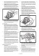
1 1 2 3 4 2 3 4 ► 1 . Hex bolt 2. Outer flange 3. Inner flange 4. Circular saw blade WARNING: If the inner flange is removed, be sure to install it on the spindle. When installing, choose a correct side on which protrusion fits into the saw blade hole perfectly. Mounting the blade on the wrong side can result in the dangerous vibration. ► 1 . Lock-off button 2. Locking lever 3. Lock pin 4. Hole for lock pin 2.
Connecting a vacuum cleaner Optional accessory When you wish to perform clean cutting operation, connect a Makita vacuum cleaner to your tool. Connect a hose of the vacuum cleaner to the dust nozzle using the front cuffs 24. 1 2 3 Hold the tool firmly. The tool is provided with both a front grip and rear handle. Use both to best grasp the tool. If both hands are holding saw, they cannot be cut by the circular saw blade.
1 1 ► 1 . Slide lever 2 Sub base (Guide rule) 1 Optional accessory By using the sub base as a guide rule, you can perform extra-accurate straight cuts. Loosen the clamping screws and slide the sub base out from the tool then insert it upside down. 1 ► 1 . Clamping screw 2. Sub base Plunge cutting (Cutting-out) WARNING: To avoid a kickback, be sure to observe the following instructions. 1 1 2 ► 1 . Rear edge of tool base 2.
2. Adjust the blade angle. 0° 1 45° 2 1 1 ► 1 . Front cutting point (165 mm blade) 2. Rear cutting point (165 mm blade) ► 1 . Triangular rule Guide device To adjust the 0°-cut accuracy, make the base perpendicular to the blade using a triangular rule, square rule, etc. by turning the adjusting bolt. Optional accessory Use of the bevel guide allows exact miter cuts with angles and fitting works. Use of the clamp ensures firm hold of workpiece on the table.
This Warranty gives you specific legal rights, and you may also have other rights which vary from state to state. Some states do not allow the exclusion or limitation of incidental or consequential damages, so the above limitation or exclusion may not apply to you. Some states do not allow limitation on how long an implied warranty lasts, so the above limitation may not apply to you.
ESPAÑOL (Instrucciones originales) ESPECIFICACIONES Modelo: XPS01 Diámetro del disco Profundidad de corte máxima 165 mm (6-1/2″) a 0° 56 mm (2-3/16″) bisel a 45° 40 mm (1-9/16″) bisel a 48° 38 mm (1-1/2″) Velocidad sin carga 2 500 r/min - 6 300 r/min Longitud total 346 mm (13-5/8″) Tensión nominal 36 V c.c.
6. 7. Si no es posible evitar usar una herramienta eléctrica en condiciones húmedas, utilice un alimentador protegido con interruptor de circuito de falla a tierra (ICFT). El uso de un ICFT reduce el riesgo de descarga eléctrica. Las herramientas eléctricas pueden producir campos electromagnéticos (CEM) que no son dañinos para el usuario.
Utilice las herramientas eléctricas solamente con las baterías designadas específicamente para ellas. La utilización de cualquier otra batería puede crear un riesgo de lesiones o incendio. Cuando no se esté usando la batería, manténgala alejada de otros objetos metálicos, como sujetapapeles (clips), monedas, llaves, clavos, tornillos u otros objetos pequeños de metal los cuales pueden actuar creando una conexión entre las terminales de la batería.
1. 2. 3. 4. Sujete la sierra firmemente con las dos manos y coloque sus brazos de forma que ofrezcan resistencia a la fuerza del retroceso brusco. Coloque su cuerpo hacia cualquiera de los lados del disco, pero no en línea con él. El retroceso brusco puede provocar que la sierra salte hacia atrás; no obstante, el operador puede controlar la fuerza del retroceso brusco si toma las precauciones adecuadas.
3. 4. Asegúrese de que la placa de base de la sierra no se mueva al realizar el “corte de inmersión”. El desplazamiento lateral del disco causará un atascamiento y posiblemente un retroceso brusco. Antes de dejar la sierra en el banco o en el suelo, observe siempre que el protector esté cubriendo el disco. Un disco desprotegido, girando por inercia, hará que la sierra se desplace hacia atrás, cortando todo lo que encuentre a su paso.
Símbolos A continuación se muestran los símbolos utilizados para la herramienta. volts o voltios corriente directa o continua 11. GUARDE ESTAS INSTRUCCIONES. velocidad sin carga revoluciones o alternaciones por minuto, frecuencia de rotación PRECAUCIÓN: Utilice únicamente baterías originales de Makita. El uso de baterías no originales de Makita, o de baterías alteradas, puede ocasionar que las baterías exploten causando un incendio, lesiones personales y daños.
Sistema de protección para la herramienta/batería DESCRIPCIÓN DEL FUNCIONAMIENTO PRECAUCIÓN: Asegúrese siempre de que la herramienta esté apagada y el cartucho de batería haya sido extraído antes de realizar cualquier ajuste o comprobación en la herramienta. Instalación o extracción del cartucho de batería La herramienta está equipada con un sistema de protección para la herramienta/batería.
Estado del indicador de batería Encendido Apagado Capacidad restante de la batería Parpadeando NOTA: Dependiendo de las condiciones de uso y la temperatura ambiente, la indicación podrá diferir ligeramente de la capacidad real. Función de cambio de velocidad automática 50% a 100% 20% a 50% Esta herramienta cuenta con “modo de alta velocidad” y “modo de alta torsión”. La herramienta cambia automáticamente el modo de operación en función de la carga de trabajo.
Para obtener cortes más limpios y seguros, ajuste la profundidad de corte de forma que no sobresalga más de un diente del disco por debajo de la pieza de trabajo. El uso de una profundidad de corte adecuada ayuda a reducir la posibilidad de que se produzca un peligroso RETROCESO BRUSCO que pueda ocasionar lesiones personales. Corte en bisel Afloje los tornillos de fijación. Ajuste el ángulo deseado inclinando según corresponda, después apriete los tornillos de fijación firmemente. 1 1 2 1 2 ► 1 .
Guía visual A B 1 1 2 ► 1 . Tope de seguridad 2. Tornillo de fijación Corte en bisel a 48° ► 1 . Base Para realizar un corte en bisel a 48°, afloje los tornillos de fijación e incline totalmente la palanca en dirección de la flecha que se muestra en la ilustración. Luego ajuste el ángulo de bisel a 48° y apriete los tornillos de fijación. La línea de corte varía en función del ángulo de corte y de si se utiliza el carril guía (accesorio opcional).
2 1 Número Velocidad de rotación del disco por minuto (r/min) 1 2 500 r/min 2 2 900 r/min 3 3 900 r/min 4 4 900 r/min 5 6 300 r/min PRECAUCIÓN: El selector de ajuste de velocidad no debe usarse para discos de la sierra con una velocidad menor especificada, sino para obtener una velocidad adecuada para el material de la pieza de trabajo. Utilice únicamente discos de la sierra marcados con al menos la velocidad sin carga máxima indicada en las ESPECIFICACIONES. ► 1 . Gatillo interruptor 2.
2. Presione el bloqueo del eje por completo de forma que el disco no pueda girar y use la llave hexagonal para aflojar el perno hexagonal. 2 3 1 1 4 ► 1 . Llave Allen (hexagonal) Extracción o instalación del disco de la sierra circular PRECAUCIÓN: Asegúrese de que el disco de la sierra circular esté instalado con los dientes orientados hacia arriba en la parte delantera de la herramienta. ► 1 . Bloqueo del eje 2. Llave hexagonal 3. Apretar 4. Aflojar 3.
Corte de secciones (corte habitual) ADVERTENCIA: ASEGÚRESE DE APRETAR BIEN EL PERNO HEXAGONAL. Asimismo, tenga cuidado de no apretar el perno con demasiada fuerza. Si su mano llegara a resbalarse de la llave hexagonal podría ocasionarle una lesión. Limpieza del protector del disco Al cambiar el disco de la sierra circular, asegúrese de limpiar también el aserrín acumulado en el protector del disco, tal como se indica en la sección de Mantenimiento.
1 1 1 ► 1 . Tornillos de ajuste Cuando realice cortes en bisel con el carril guía, utilice la palanca deslizable para evitar que la herramienta se caiga. Mueva la palanca deslizable sobre la base de la herramienta en la dirección de la flecha de manera que encaje en la ranura del corte al ras en el carril guía. 2 ► 1 . Tornillo de fijación 2.
Corte de inmersión (recorte) Dispositivo de guía ADVERTENCIA: Para evitar un retroceso brusco, asegúrese de seguir las instrucciones a continuación. Accesorio opcional El uso de la guía de bisel permite realizar cortes en inglete con ángulos y encajes exactos. El uso de la pinza asegura una sujeción firme de la pieza de trabajo sobre la mesa.
Para ajustar la precisión de corte a 0°, haga que la base quede perpendicular al disco usando una regla triangular o escuadra, etc. girando el perno de ajuste. 1 • • • • • • • • • • Disco de la sierra circular Base inferior Llave Allen (hexagonal) Carril guía Guía de bisel Pinza Hoja Hoja de hule Hoja de posición Batería y cargador originales de Makita NOTA: Algunos de los artículos en la lista pueden incluirse en el paquete de la herramienta como accesorios estándar. Éstos pueden variar de país a país.
< USA only > WARNING Some dust created by power sanding, sawing, grinding, drilling, and other construction activities contains chemicals known to the State of California to cause cancer, birth defects or other reproductive harm. Some examples of these chemicals are: • lead from lead-based paints, • crystalline silica from bricks and cement and other masonry products, and • arsenic and chromium from chemically-treated lumber.