INSTRUCTION MANUAL MANUAL DE INSTRUCCIONES Cordless Rotary Hammer Martillo Rotativo Inalámbrico XRH07 IMPORTANT: Read Before Using. IMPORTANTE: Lea antes de usar.
ENGLISH (Original instructions) SPECIFICATIONS Model: Capacities XRH07 Carbide-tipped bit 40 mm (1-9/16") Core bit 105 mm (4-1/8") No load speed (RPM) 250 - 500/min Blows per minute 1,450 - 2,900/min Overall length 473 mm (18-5/8") Rated voltage D.C. 36 V Net weight • • • 7.3 - 8.1 kg (16.1 - 17.9 lbs) Due to our continuing program of research and development, the specifications herein are subject to change without notice.
2. 3. 4. 5. 6. 7. 8. 9. Use personal protective equipment. Always wear eye protection. Protective equipment such as dust mask, non-skid safety shoes, hard hat, or hearing protection used for appropriate conditions will reduce personal injuries. Prevent unintentional starting. Ensure the switch is in the off-position before connecting to power source and/or BATTERY pack, picking up or carrying the tool.
CORDLESS ROTARY HAMMER SAFETY WARNINGS 1. 2. 3. 4. 5. 6. 7. 8. 9. 10. 11. 12. 13. 14. 15. Symbols The followings show the symbols used for tool. Wear ear protectors. Exposure to noise can cause hearing loss. Use auxiliary handle(s), if supplied with the tool. Loss of control can cause personal injury. Hold power tool by insulated gripping surfaces, when performing an operation where the cutting accessory may contact hidden wiring.
11. 12. Follow your local regulations relating to disposal of battery. Use the batteries only with the products specified by Makita. Installing the batteries to non-compliant products may result in a fire, excessive heat, explosion, or leak of electrolyte. 12. 13. 14. SAVE THESE INSTRUCTIONS. CAUTION: Only use genuine Makita batteries. Use of non-genuine Makita batteries, or batteries that have been altered, may result in the battery bursting causing fires, personal injury and damage.
Indicating the remaining battery capacity FUNCTIONAL DESCRIPTION Only for battery cartridges with the indicator CAUTION: Always be sure that the tool is switched off and the battery cartridge is removed before adjusting or checking function on the tool. Installing or removing battery cartridge 1 CAUTION: Always switch off the tool before installing or removing of the battery cartridge. 2 CAUTION: Hold the tool and the battery cartridge firmly when installing or removing battery cartridge.
Tool / battery protection system Speed change The tool is equipped with a tool/battery protection system. This system automatically cuts off power to the motor to extend tool and battery life. The tool will automatically stop during operation if the tool or battery is placed under one of the following conditions: The revolutions and blows per minute can be adjusted by turning the adjusting dial. The dial is marked 1 (lowest speed) to 5 (full speed).
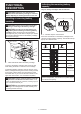
Hammering only Lighting up the front lamp For chipping, scaling or demolition operations, rotate the action mode changing knob to the symbol. Use a bull point, cold chisel, scaling chisel, etc. 1 2 1 ► 1. Lamp CAUTION: Do not look in the light or see the source of light directly. ► 1. Pointer 2. Action mode changing knob Pull the switch trigger to light up the lamp. The lamp keeps on lighting while the switch trigger is being pulled.
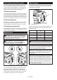
ASSEMBLY CAUTION: Always be sure that the tool is switched off and the battery cartridge is removed before carrying out any work on the tool. Side handle 1 ► 1. Side grip Grease Coat the shank end of the drill bit beforehand with a small amount of grease (about 0.5 - 1 g). This chuck lubrication assures smooth action and longer service life. Installing or removing drill bit CAUTION: Use the side handle only when Clean the shank end of the drill bit and apply grease before installing the drill bit.
Depth gauge The depth gauge is convenient for drilling holes of uniform depth. Press and hold the lock button, and then insert the depth gauge into the hex hole. 1 1 2 2 ► 1. Drill bit 2. Chuck cover Chisel angle (when chipping, scaling or demolishing) The chisel can be secured at the desired angle. To change the chisel angle, rotate the action mode changing knob to the O symbol. Turn the chisel to the desired angle. ► 1. Depth gauge 2.
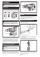
Connecting the tool to the vacuum cleaner Dust extractor attachment Optional accessory 1. Attach the holder joint to the tool, and then attach the hose holder to the holder joint. Installing the dust extractor attachment 1. Loosen the side grip on the tool. 2. Install the dust cover so that the claws of the dust cover fit in the grooves between the tool and the side grip. 1 1 2 3 2 ► 1. Dust cover 2. Claw 3. Groove 3. Tighten the side grip securely. 4.
Using depth gauge for drilling operation 1 When you stack two bellows, attach the depth gauge extension to the depth gauge. 1 2 3 ► 1. Hose holder 2. Shaft 3. Side grip ► 1. Depth gauge extension 2. Attach the holder joint to the tool, and then attach the hose holder to the holder joint. Dust extractor attachment (for hammering only) Optional accessory 1. Install the hose holder. When the side handle is installed to tool, loosen the clamp nut, and then remove the hex bolt.
3. Attach the dust cover and the hose to the tool, and then fix the hose to the hose holders. 1 2 OPERATION CAUTION: Always use the side grip (auxiliary handle) and firmly hold the tool by both side grip and switch handle during operations. 3 CAUTION: Always make sure that the workpiece is secured before operation. 3 CAUTION: Do not pull the tool out forcibly even the bit gets stuck. Loss of control may cause injury.
Chipping/Scaling/Demolition Set the action mode changing knob to the symbol. Hold the tool firmly with both hands. Turn the tool on and apply slight pressure on the tool so that the tool will not bounce around, uncontrolled. Pressing very hard on the tool will not increase the efficiency. WIRELESS ACTIVATION FUNCTION Optional accessory What you can do with the wireless activation function The wireless activation function enables clean and comfortable operation.
1. Open the lid on the tool as shown in the figure. 1 2 3 1 ► 1. Lid 2. Insert the wireless unit to the slot and then close the lid. ► 1. Wireless unit 2. Hook 3. Lid When inserting the wireless unit, align the projections with the recessed portions on the slot. After removing the wireless unit, keep it in the supplied case or a static-free container. 2 NOTICE: Always use the hooks on the back of the lid when removing the wireless unit.
2. Set the stand-by switch on the vacuum cleaner to "AUTO". NOTE: The wireless activation lamps finish blinking in green after 20 seconds elapsed. Press the wireless activation button on the tool while the wireless activation lamp on the cleaner is blinking. If the wireless activation lamp does not blink in green, push the wireless activation button briefly and hold it down again. NOTE: When performing two or more tool registrations for one vacuum cleaner, finish the tool registration one by one.
5. Pull the switch trigger of the tool. Check if the vacuum cleaner runs while the switch trigger is being pulled. 4. Push the wireless activation button on the tool briefly. The wireless activation lamp will blink in blue. To stop the wireless activation of the vacuum cleaner, push the wireless activation button on the tool. 2 NOTE: The wireless activation lamp on the tool will stop blinking in blue when there is no operation for 2 hours.
If the cancellation is performed successfully, the wireless activation lamps will light up in red for 2 seconds and start blinking in blue. Cancelling tool registration for the vacuum cleaner Perform the following procedure when cancelling the tool registration for the vacuum cleaner. 1. Install the batteries to the vacuum cleaner and the tool. 2. Set the stand-by switch on the vacuum cleaner to "AUTO". NOTE: The wireless activation lamps finish blinking in red after 20 seconds elapsed.
Troubleshooting for wireless activation function Before asking for repairs, conduct your own inspection first. If you find a problem that is not explained in the manual, do not attempt to dismantle the tool. Instead, ask Makita Authorized Service Centers, always using Makita replacement parts for repairs. State of abnormality Probable cause (malfunction) Remedy The wireless activation lamp does not light/blink. The wireless unit is not installed into the tool.
MAINTENANCE CAUTION: Always be sure that the tool is switched off and the battery cartridge is removed before attempting to perform inspection or maintenance. NOTICE: Never use gasoline, benzine, thinner, alcohol or the like. Discoloration, deformation or cracks may result. To maintain product SAFETY and RELIABILITY, repairs, any other maintenance or adjustment should be performed by Makita Authorized or Factory Service Centers, always using Makita replacement parts.
ESPAÑOL (Instrucciones originales) ESPECIFICACIONES Modelo: Capacidades XRH07 Punta de carburo 40 mm (1-9/16″) Punta de corona 105 mm (4-1/8″) Velocidad sin carga (RPM) 250 r/min - 500 r/min Golpes por minuto 1 450 gpm - 2 900 gpm Longitud total 473 mm (18-5/8″) Tensión nominal 36 V c.c. Peso neto • • • 7,3 kg - 8,1 kg (16,1 lbs - 17,9 lbs) Debido a nuestro continuo programa de investigación y desarrollo, las especificaciones aquí incluidas están sujetas a cambio sin previo aviso.
4. 5. 6. 7. No maltrate el cable. Nunca utilice el cable para transportar, jalar o desconectar la herramienta eléctrica. Mantenga el cable alejado del calor, aceite, objetos cortantes o piezas móviles. Los cables dañados o enredados aumentan el riesgo de sufrir una descarga eléctrica. Cuando utilice una herramienta eléctrica en exteriores, utilice un cable de extensión apropiado para uso en exteriores.
8. 9. Mantenga los mangos y superficies de asimiento secos, limpios y libres de aceite o grasa. Los mangos y superficies de asimiento resbalosos no permiten una manipulación segura ni el control de la herramienta en situaciones inesperadas. Cuando vaya a utilizar esta herramienta, evite usar guantes de trabajo de tela ya que éstos podrían atorarse. Si los guantes de trabajo de tela llegaran a atorarse en las piezas móviles, esto podría ocasionar lesiones personales.
15. Asegúrese siempre de que la herramienta esté apagada y de que el cartucho de batería y la punta hayan sido extraídos antes de pasarle la herramienta a otra persona. GUARDE ESTAS INSTRUCCIONES. 6. 7. 8. ADVERTENCIA: NO DEJE que la comodidad o familiaridad con el producto (a base de utilizarlo repetidamente) evite que siga estrictamente las normas de seguridad para dicho producto.
22. Instrucciones importantes de seguridad para la unidad inalámbrica 1. 2. 3. 4. 5. 6. 7. 8. 9. 10. 11. 12. 13. 14. 15. 16. 17. 18. 19. 20. 21. No desarme ni modifique la unidad inalámbrica. Mantenga la unidad inalámbrica alejada de los niños pequeños. En caso de ingerirla accidentalmente, solicite atención médica de inmediato. Utilice la unidad inalámbrica solamente con herramientas de Makita. No exponga la unidad inalámbrica a la lluvia ni a condiciones de humedad.
Indicación de la capacidad restante de la batería DESCRIPCIÓN DEL FUNCIONAMIENTO PRECAUCIÓN: Asegúrese siempre de que la herramienta esté apagada y el cartucho de batería haya sido extraído antes de realizar cualquier ajuste o comprobación en la herramienta. Únicamente para cartuchos de batería con el indicador Instalación o extracción del cartucho de batería 1 PRECAUCIÓN: Apague siempre la herramienta antes de colocar o quitar el cartucho de batería.
Sistema de protección para la herramienta/batería La herramienta está equipada con un sistema de protección de la herramienta/batería. Este sistema corta en forma automática el suministro de energía al motor para prolongar la vida útil de la herramienta y la batería.
Selección del modo de accionamiento PRECAUCIÓN: No gire el selector de ajuste cuando la herramienta esté funcionando. De lo contrario, podría resultar en la pérdida de control de la herramienta y ocasionar una lesión. AVISO: No gire la perilla de cambio de modo de accionamiento cuando la herramienta esté en marcha. Esto podría causar daños a la herramienta.
Limitador de torsión 1 AVISO: En cuanto el limitador de torsión se accione, apague de inmediato la herramienta. Esto ayudará a evitar el desgaste prematuro de la herramienta. AVISO: Las brocas tales como las de sierra perforadora, las cuales tienden a atorarse o engancharse fácilmente en el agujero, no son adecuadas para esta herramienta. Esto es debido a que pueden provocar que el limitador de torsión se accione con demasiada frecuencia.
Instalación o extracción de la broca Ángulo del cincel (durante el cincelado, desincrustación o demolición) Limpie el extremo de la espiga de la broca y aplique grasa antes de instalar la broca. El cincel puede fijarse en el ángulo deseado. Para cambiar el ángulo del cincel, gire la perilla de cambio de modo de accionamiento al símbolo O. Gire el cincel al ángulo deseado. 2 1 1 2 ► 1. Extremo de la espiga 2. Grasa Inserte la broca en la herramienta.
4. Instale el fuelle o extensión para la cubierta contra polvo adecuados para su trabajo. Cuando utilice un fuelle, instale la junta a su parte superior. Cuando apile dos fuelles, conéctelos con la junta. Asegúrese de que el lado dentado del calibrador de profundidad quede de frente a la marca. 1 2 1 2 ► 1. Marca 2. Lado dentado Ajuste el calibrador de profundidad moviéndolo hacia atrás y hacia adelante mientras oprime el botón de bloqueo.
2. Fije la manguera en el sujetador de la manguera. Accesorio del extractor de polvo (únicamente para percusión) Accesorio opcional 1. Instale el sujetador de la manguera. Cuando el mango lateral esté instalado en la herramienta, afloje la tuerca de fijación y luego extraiga el perno hexagonal. Instale el sujetador de la manguera con el perno hexagonal y la tuerca de fijación apretando la tuerca de fijación firmemente. 1 1 ► 1.
2. Coloque la junta del sujetador en la herramienta y luego coloque el sujetador de la manguera en la junta del sujetador. 5. Ajuste la distancia entre la cubierta contra polvo y la punta del cincel o cincel de punta. La distancia recomendada es de 30 mm (1-3/16″) a 100 mm (3-15/16″). (1) 1 2 ► (1) 30 mm (1-3/16″) a 100 mm (3-15/16″) OPERACIÓN ► 1. Junta del sujetador 2.
Operación de taladrado con percusión Soplador Accesorio opcional Después de perforar el agujero, utilice el soplador para limpiar el polvo del agujero. PRECAUCIÓN: En el momento de comenzar a penetrar, cuando se obstruye el orificio con virutas y partículas, o cuando se topa contra varillas de refuerzo de concreto, se ejerce una tremenda y repentina fuerza de torsión sobre la herramienta/ broca.
Instalación de la unidad inalámbrica 2 Accesorio opcional PRECAUCIÓN: Coloque la herramienta sobre una superficie plana y estable cuando vaya a instalar la unidad inalámbrica. AVISO: Limpie el polvo y la suciedad en la herramienta antes de instalar la unidad inalámbrica. El polvo o la suciedad podrían causar una avería si llegan a introducirse en la ranura de la unidad inalámbrica.
Registro de la herramienta para la aspiradora NOTA: Para el registro de la herramienta, se requiere una aspiradora Makita compatible con la función de activación inalámbrica. 1 2 NOTA: Termine de instalar la unidad inalámbrica en la herramienta antes de comenzar con el registro de la herramienta. NOTA: Durante el registro de la herramienta, no jale el gatillo interruptor ni active el interruptor de encendido en la aspiradora. NOTA: Consulte también el manual de instrucciones de la aspiradora.
5. Jale el gatillo interruptor de la herramienta. Verifique que la aspiradora funcione mientras jala el gatillo interruptor. 2. Conecte la manguera de la aspiradora a la herramienta. Para detener la activación inalámbrica de la aspiradora, oprima el botón de activación inalámbrica en la herramienta. NOTA: La luz indicadora de activación inalámbrica en la herramienta dejará de parpadear en azul cuando no haya operación durante 2 horas.
Descripción del estado de la luz indicadora de activación inalámbrica 1 ► 1. Luz indicadora de activación inalámbrica La luz indicadora de activación inalámbrica muestra el estado de la función de activación inalámbrica. Consulte la tabla a continuación para ver qué significa el estado de la luz indicadora.
Si la cancelación se realiza exitosamente, las luces indicadoras de activación inalámbrica se encenderán en rojo durante 2 segundos y comenzarán a parpadear en azul. Cancelación del registro de la herramienta para la aspiradora Realice el siguiente procedimiento para cancelar el registro de la herramienta para la aspiradora. 1. Instale las baterías en la aspiradora y en la herramienta. 2. Ajuste el interruptor de modo en espera en la aspiradora en “AUTO”.
Detección y solución de problemas para la función de activación inalámbrica Antes de solicitar alguna reparación, primero realice una inspección por su cuenta. Si detecta algún problema que no esté explicado en el manual, no intente desensamblar la herramienta. En vez de esto, solicite la reparación a un centro de servicio autorizado de Makita, usando siempre piezas de repuesto Makita. Estado de la anomalía Causa probable (avería) Remedio La luz indicadora de activación inalámbrica no enciende/parpadea.
Estado de la anomalía Causa probable (avería) Remedio La aspiradora no funciona junto con el interruptor de la herramienta. La unidad inalámbrica no está instalada en la herramienta. La unidad inalámbrica está instalada incorrectamente en la herramienta. Instale la unidad inalámbrica correctamente. La terminal de la unidad inalámbrica y/o la ranura está sucia. Retire con cuidado el polvo y la suciedad en la terminal de la unidad inalámbrica y limpie la ranura.
NOTA: Algunos de los artículos en la lista pueden incluirse en el paquete de la herramienta como accesorios estándar. Éstos pueden variar de país a país. GARANTÍA LIMITADA DE MAKITA Ésta Garantía no aplica para México Consulte la hoja de la garantía anexa para ver los términos más vigentes de la garantía aplicable a este producto. En caso de no disponer de esta hoja de garantía anexa, consulte los detalles sobre la garantía descritos en el sitio web de su país respectivo indicado a continuación.
< USA only > WARNING Some dust created by power sanding, sawing, grinding, drilling, and other construction activities contains chemicals known to the State of California to cause cancer, birth defects or other reproductive harm. Some examples of these chemicals are: • lead from lead-based paints, • crystalline silica from bricks and cement and other masonry products, and • arsenic and chromium from chemically-treated lumber.