
Installation Guide

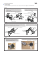
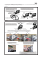
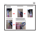
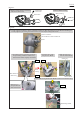
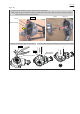

Table Of Contents

P 10/ 19
3 Loop handle set, Pipe complete, Grip set, Switch lever, Lock off lever
3-1 Disassembling
Fig. 3-1-1 Fig. 3-1-2
Fig. 3-1-3
See Figs. 3-1-1, 3-1-2, 3-1-3 as follows and Figs. 3-1-4, 3-1-2, 3-1-3 in the next page.
Note: No need to remove Nylon cutting head / Plastic blade from Motor housing.
4. Disconnect the connectors of Power supply cord unit (long)
from the connectors of Controller complete in Housing L.
Battery
guard
2. Remove Battery guard
by unscrewing
three M4x12 + Screws.
1. Disassemble Roop handle set.
3. Remove Housing R by unscrewing seven 4x18 Tapping screws.
Housing R
Controller complete
5. To remove Power supply cord unit (long) completely
from the lead wires of Controller complete, cut three
Insulated connectors 5.5-SD at the portion designated
with red lines.
Note: Cut each clamped portion to leave the lead wires
because of the easy reassembling process.
M4x12 + Screw
(3 pcs.)
M5x25 Hex socket
head screw (2 pcs.)
Clamp cover B
Clamp 33
Clamp 33
Roop handle set
Roop handle
Pipe complete
(It is not included in Loop handle set.)
4x18 Tapping screw (7 pcs.)
Clamped portions of
Insulated connectors 5.5-SD (3 pcs.)
6. Disconnect the connector of Power supply cord unit
(short) from the connector of Contoller complete.
7. Remove Strain relief by unscrewing 4x18 Tapping
screw. Power supply cord (short) is removed together
with Corrugated tube.
Connector of Power supply cord (short)
4x18
Tapping
screw
Strain relief
Power supply cord unit
(long)
Power supply cord
unit (short) with
Corrugated tube