
Installation Guide
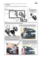


Table Of Contents

P 13/ 19
Fig. 3-2-2
Torsion spring 9
1. Insert Lock off lever halfway over the boss of Grip L
while pressing Torsion spring 9.
2. Push Lock off lever to the bottom of Grip L after holding
the Torsion spring’s arm with the rib of Grip L.
Boss of Grip L Lock off lever
Rib of Grip L
3. Assemble Lock off lever by fitting its projection to the groove in Grip L as shown in the following four pictures.
Projection of Lock off lever
Groove in Grip L
Viewed from the inside
Lock off lever
Rib of Grip L Groove of Grip L
Switch lever
4. Insert Switch lever over the pin of Grip L until it stops while
pressing the arm of Torsion spring 10 to the rib of Grip L.
5. Push Switch lever in direction of the yellow arrow
until the projection is fit into the groove in Grip L.
Viewed from Sub controller/ the upper side of Lock off lever
Push and align the projection of
Lock off lever.
Torsion spring 10
Pin of Grip L Groove of Grip L
Projection of Switch lever