
Installation Guide
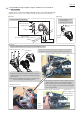


Table Of Contents

P 15/ 19
Fig. 5-1
Put Connectors to the space between the bottom of Motor housing
and Power supply cord unit (long).
Connectors
Power supply cord unit (long)
Wiring in Motor housing
A
A
Strain relief
Connectors
The bottom of
Motor housing
Motor housing
Strain relief
Section A-A
Power supply cord
unit (long)
Mount Strain relief while facing its looped side
to the bottom of Motor housing.
Insulated connector 5.5-SD
Insulated connector 5.5-SD
Power supply cord unit (long) has to be fixed with the end
protruding from Strain relief in the direction of Controller B.
End of Power supply cord unit (long)
Strain relief
Controller B
Put Insulated connectors 5.5-SD and sags
of lead wires to the drawn place between
Controller B and Power supply cord unit.
Looped side of Strain relief Looped side of Strain relief
End of Power supply cord unit (long)
Strain relief
Controller B
5 CIRCUIT DIAGRAM