
Installation Guide
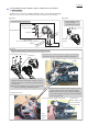


Table Of Contents

P 16/ 19
Fig. 5-2
Wiring in Grip set
Switch unit
Lead wires of
Power supply cord unit
(short) to Sub controller
Set the connector on blue lead
wires and black lead wires
to the connector for
Switch unit as drawn.
Set the connector of Sub controller and the connector on the one of
Power supply cord unit (short) as drawn.
Sub controller
Rib C
Rib B
Rib A
Heat shrink tube
Sub controller
Corrugated tube
with Power supply
cord unit (short)
Strain relief
Note: Be careful not to pinch Corrugated tube of
Power supply cord unit (short) with Strain relief .
Do not put the sag of any Lead wires
on Connectors.
Do not put the sag of Lead wires on the connectors.
First, set lead wires of
Switch unit to Grip set.
The Lead wires for Sub controller have to be put
so that the end of Heat shrink tube protrudes
from the border line of Rib A.
Put Lead wires with tape between
Rib C and Rib B.