
Installation Guide
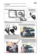


Table Of Contents

Fix Power supply cord unit (long) by pulling out at least 3 mm from the end of Rib D as shown.
Flag receptacles of Terminal A and
Terminal B have to be connected
so that their wire connecting portions
are located over the marks of + - poles.
Housing L side
Terminal A
Terminal B
Wire connecting portions
3 mm
Corrugated tube
Strain relief
Power supply cord unit (short)
Controller
Rib A
Rib B
Rib C
Rib D
Rib E
Flag
receptacles
P 17/ 19
Fig. 5-3
Put Power supply cord (long) between Rib D and Rib E.
Put lead wires with Insulated
connectors 5.5-SD in front
of Noise suppressor.
(between Noise suppressor
and Housing R)
Put lead wires of Terminals
between Rib A and Rib B,
and Rib B and Rib C.
Put Lead wires for 10 pin Connector
between Rib B and Rib C.
Place 2 pin / 5 pin connectors here.
Wiring in Housing set
Insulated
connectors
5.5-SD
10 pin Connector
Be careful not to pinch Corrugated tube
on Power supply cord unit (short) with
Strain relief .