
Installation Guide

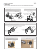
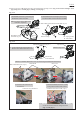
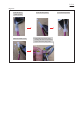
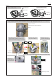
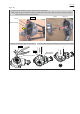

Table Of Contents

Fig. 2-1-4
Fig. 2-1-5
M5x20 Hex socket
head bolts (2 pcs.)
M5x16 Hex socket head bolts with WR* (2 pcs.)
1. Disassemble Protector by loosening two
M5x20 Hex socket head bolts.
Note: No need to remove Hex socket
head bolts completely.
2. Disassemble Protector clamp by unscrewing
two M5x16 Hex socket head bolts with WR*.
Protector
Protector clamp
< Protector>
P 4/ 19
1. Loosen M5x25 Hex socket head bolt.
Remove three M5x20 Pan head screws.
2. Remove Top cover.
Top cover
M5x20 Pan head screw (3 pcs.)
M4x16 Pan head screw (2 pcs.)
Controller B
5. Cut three Insulated connectors 5.5-SD
at the position marked with red lines.
Inner cover
M5x25 Hex
socket head bolt
3. Remove Controller B and Inner cover by unscrewing two M4x16 Pan head screws.
Note: Lead wires connected with Insulated connectors 5.5-SD
can be disconnected without cutting lead wires.
(Fig. 2-1-6 in page 5)
4. Disconnect the connectors of
Controller B.
Connectors of Controller B
Insulated connectors 5.5-SD (3 pcs.)
(2) Remove Protector. (Fig. 2-1-4) And then, disassemble Motor housing section. (Fig. 2-1-5 as below and Fig. 2-1-6 in
page 5, Figs 2-1-7/ 2-1-8 in page 6, and Fig. 2-1-9 in page 7)
*W...Spring washer
R....Flat washer