
Installation Guide

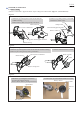
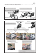
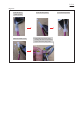
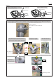
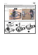
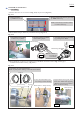

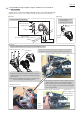
Table Of Contents

P 8/ 19
Fig. 2-2-2
Fig. 2-2-3
1. Mount Ball bearing 607ZZ
to Stator ass’y by hand.
2. Set Motor housing on 1R023
while avoiding its pin.
(1) If Stator lead wires are cut as shown in Fig. 2-1-5, strip the ends. (Fig. 2-2-1)
(2) Mount Ball bearings to Stator ass’y and Motor housing. (Fig. 2-2-2)
(3) Mount Retaining ring R-28 to secure Ball bearing 6001DDW with 1R291. Refer to Fig. 2-1-9 in page 7.
Assemble Rotor to Motor housing. (Fig. 2-2-3)
3. Assemble Ball bearing 6001DDW
by pressing down 1R031.
Pin
Ball bearing 6001DDW
Stator ass’y
1R023
1R031
Motor housing
Fig. 2-2-1
1. Remove sheathes
by 13mm from the tip.
2. Remove enamel with abrasive paper #100
by 11mm from the tip.
Note: It is necessary to remove enamel
to conduct electricity.
1. Place Ring 14 on the shaft of Rotor.
Note: No paint portion of Ring 14 must be faced to Rotor.
1R027
1R028
2. Insert the shaft of Rotor into
the bearing in Motor housing.
3. Support Motor housing with 1R027.
Press down 1R028 while applying
1R028 on the bearing to assemble
Rotor into Motor housing.
Rotor
Shaft of Rotor
No paint portion
painted
in green
[cross section]
no paint
Motor housing
Ball bearing 607ZZ
Motor housing
Note: Be sure to
avoid the pin
from 1R023.
2 ROTOR, STATOR ASS’Y
2-2 Assembling
Ring 14