INSTRUCTION MANUAL MANUAL DE INSTRUCCIONES Cordless Grass Trimmer Cortador Inalámbrico de Pasto XRU15 IMPORTANT: Read Before Using. IMPORTANTE: Lea antes de usar.
ENGLISH (Original instructions) SPECIFICATIONS Model: XRU15 Handle type No load speed (at each rotation speed level) Loop handle Nylon cutting head 3: 6,500 /min 2: 5,300 /min 1: 3,500 /min Overall length (without cutting tool) 1,758 mm (69-1/4″) Nylon cord diameter Applicable cutting tool and cutting diameter 2.0 - 2.3 mm (0.08 - 0.09″) Nylon cutting head (P/N: 197296-3) 380 mm (15″) Rated voltage D.C. 36 V Net weight • • • 3.9 - 4.5 kg (8.6 - 10.
10. 11. 12. Stay Alert - Watch what you are doing. Use common sense. Do not operate appliance when you are tired. Store idle appliances indoors. Keep fingers away from switch trigger when not operating the tool and when moving from one operating position to another. Intended use of the tool 1. Use right tool. The cordless string trimmer is only intended for cutting grass and light weeds. It should not be used for any other purpose such as edging or hedge cutting as this may cause injury. 2.
9. 10. 11. 12. 13. 14. 15. Do not expose a battery pack or machine to fire or excessive temperature. Exposure to fire or temperature above 130°C (265°F) may cause explosion. Follow all charging instructions and do not charge the battery pack or machine outside of the temperature range specified in the instructions. Charging improperly or at temperatures outside of the specified range may damage the battery and increase the risk of fire.
17. 18. 19. 20. 21. 22. 23. 24. 25. 26. Cutting elements continue to rotate after the motor is switched off. Do not operate power tools in explosive atmospheres, such as in the presence of flammable liquids, gases or dust. Power tools create sparks which may ignite the dust or fumes. Take a rest to prevent loss of control caused by fatigue. We recommend to take a 10 to 20-minute rest every hour. Hold the power tool by insulated gripping surfaces only, because the cutting tool may contact hidden wiring.
10. 11. 12. The contained lithium-ion batteries are subject to the Dangerous Goods Legislation requirements. For commercial transports e.g. by third parties, forwarding agents, special requirement on packaging and labeling must be observed. For preparation of the item being shipped, consulting an expert for hazardous material is required. Please also observe possibly more detailed national regulations.
PARTS DESCRIPTION 6 2 1 7 8 3 4 5 9 10 12 11 1 Speed indicator 2 ADT indicator (ADT = Automatic Torque Drive Technology) 3 Power lamp 4 Main power button 5 Reverse button 6 Battery cartridge 7 Lock-off lever 8 Switch trigger 9 Hanger 10 Handle 11 Protector (for nylon cutting head) 12 Shoulder harness 7 ENGLISH
FUNCTIONAL DESCRIPTION Status Speed indicator On Off Blinking Overload WARNING: Always be sure that the tool is switched off and the battery cartridge is removed before adjusting or checking function on the tool. Failure to switch off and remove the battery cartridge may result in serious personal injury from accidental start-up. Overheat Installing or removing battery cartridge Over discharge 3 2 3 2 3 2 CAUTION: Always switch off the tool before installing or removing of the battery cartridge.
Press the check button on the battery cartridge to indicate the remaining battery capacity. The indicator lamps light up for a few seconds. Indicator lamps Lighted Off Switch action WARNING: For your safety, this tool is equipped with lock-off lever which prevents the tool from unintended starting. NEVER use the tool if it runs when you simply pull the switch trigger without pressing the lock-off lever. Return the tool to our authorized service center for proper repairs BEFORE further usage.
Speed adjusting Indicator You can adjust the tool speed by tapping the main power button. Each time you tap the main power button, the level of speed will change. 1 Rotation speed ADT 3,500 - 6,500 /min Reverse button for debris removal WARNING: Switch off the tool and remove the battery cartridge before you remove entangled weeds or debris which the reverse rotation function can not remove.
Electronic function Hex wrench storage CAUTION: Be careful not to leave the hex wrench inserted in the tool head. It may cause injury and/or damage to the tool. Constant speed control The speed control function provides the constant rotation speed regardless of load conditions. When not in use, store the hex wrench as illustrated to keep it from being lost. Soft start feature Soft start because of suppressed starting shock.
2. Place the nylon cutting head onto the spindle and tighten it securely by hand. Installing the protector 3. WARNING: Never use the tool without the Remove the hex wrench from the tool head. To remove the nylon cutting head, follow the installation procedures in reverse. guard illustrated in place. Failure to do so can cause serious personal injury. CAUTION: Take care not to injure yourself on the cutter for cutting the nylon cord. OPERATION Attach the protector to the clamp using bolts.
3. Adjust the shoulder harness to a comfortable working position. Loosen the hex socket head bolt on the hanger. Move the hanger to a comfortable working position and then tighten the bolt. 1 2 The shoulder harness features a means of quick release. Simply squeeze the sides of the buckle to release the tool from the shoulder harness. ► 1 . Hanger 2. Hex socket head bolt Correct handling of the tool WARNING: Always position the tool on your right-hand side.
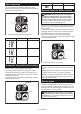
When using a nylon cutting head (bump & feed type) The nylon cutting head is a dual string trimmer head provided with a bump & feed mechanism. To feed out the nylon cord, tap the cutting head against the ground while rotating. Replace the nylon cord if it is not fed any more. The method of replacing the nylon cord varies depending on the type of the nylon cutting head. 1 ► 1 . Most effective cutting area NOTICE: The bump feed will not operate properly if the nylon cutting head is not rotating.
95-M10L 3 m (9 ft) 100 mm (3-15/16″) 80 mm (3-1/8″) 15 ENGLISH
B&F ECO 4L 3 m (9 ft) 100 mm (3-15/16″) 80 mm (3-1/8″) 16 ENGLISH
For Ultra Auto 4 3 m (9 ft) 100 mm (3-15/16″) 80 mm (3-1/8″) 17 ENGLISH
UN-74N 3 m (9 ft) 100 mm (3-15/16″) 80 mm (3-1/8″) 18 ENGLISH
Manual feed type When the nylon cord gets short, pull it out from the eyelet and feed it from the another eyelet. 0.75 m (2.
TROUBLESHOOTING Before asking for repairs, conduct your own inspection first. If you find a problem that is not explained in the manual, do not attempt to dismantle the tool. Instead, ask Makita Authorized Service Centers, always using Makita replacement parts for repairs. State of abnormality Probable cause (malfunction) Remedy Motor does not run. Battery cartridge is not installed. Install the battery cartridge. Battery problem (under voltage) Recharge the battery.
ESPAÑOL (Instrucciones originales) ESPECIFICACIONES Modelo: XRU15 Tipo de mango Velocidad sin carga (en cada nivel de la velocidad de rotación) Mango redondo Cabezal de corte de nailon 3: 6 500 r/min 2: 5 300 r/min 1: 3 500 r/min Longitud total (sin la herramienta de corte) 1 758 mm (69-1/4″) Diámetro del cordón de nailon Herramienta de corte aplicable y diámetro de corte 2,0 mm - 2,3 mm (0,08″ - 0,09″) Cabezal de corte de nailon (No. de pieza: 197296-3) 380 mm (15″) Tensión nominal 36 V c.c.
7. 8. 9. 10. 11. 12. La desbrozadora deberá apagarse inmediatamente si muestra alguna señal de operación anormal. No fuerce la herramienta. Esto permitirá hacer mejor el trabajo con un menor riesgo de lesiones a la velocidad para la que fue diseñada. No utilice la herramienta donde no alcance. Mantenga los pies sobre suelo firme y el equilibrio en todo momento. Manténgase alerta - Preste atención a lo que está haciendo. Utilice el sentido común. No utilice el aparato cuando esté cansado.
6. 7. 8. 9. 10. 11. 12. 13. 14. 15. Cuando no se esté usando el paquete de batería, manténgalo alejado de otros objetos metálicos, como sujetapapeles (clips), monedas, llaves, clavos, tornillos u otros objetos pequeños de metal que puedan crear una conexión entre una terminal y otra. Causar un cortocircuito en las terminales de la batería puede provocar quemaduras o incendio. En condiciones de mal uso, podría escapar líquido de la batería; evite el contacto.
7. 8. 9. 10. 11. 12. 13. 14. 15. 16. 17. 18. 19. 20. 21. 22. Retire la arena, piedras, clavos, etc. que encuentre en el área de trabajo. Las partículas extrañas podrían dañar el cabezal de corte de nailon. Si el cabezal de corte de nailon llega a golpear piedras u otros objetos duros, apague inmediatamente el motor e inspeccione el cabezal de corte de nailon. Antes de comenzar a cortar, el cabezal de corte de nailon deberá alcanzar su velocidad de trabajo completa.
6. ADVERTENCIA: El uso de este producto puede producir polvo que contenga sustancias químicas que podrían causar enfermedades respiratorias o de otro tipo. Algunos ejemplos de estas sustancias químicas son los compuestos encontrados en pesticidas, insecticidas, fertilizantes y herbicidas. 7. 8. El riesgo al que se expone varía, dependiendo de la frecuencia con la que realice este tipo de trabajo.
DESCRIPCIÓN DE LAS PIEZAS 6 2 1 7 8 3 4 5 9 10 12 11 1 Indicador de velocidad 2 Indicador de ADT (ADT = Automatic Torque Drive Technology (Tecnología de accionamiento automático de torsión)) 3 Luz de alimentación 4 Botón de encendido principal 5 Botón de inversión 6 Cartucho de batería 7 Palanca de desbloqueo 8 Gatillo interruptor 9 Colgador 10 Mango 11 Protector (para el cabezal de corte de nailon) 12 Arnés para hombro 26 ESPAÑOL
Sistema de protección para la herramienta/batería DESCRIPCIÓN DEL FUNCIONAMIENTO ADVERTENCIA: Asegúrese siempre de que la herramienta esté apagada y que el cartucho de batería haya sido extraído antes de realizar cualquier ajuste o revisión del funcionamiento de la herramienta. El no seguir esta indicación de apagar y quitar el cartucho de batería puede ocasionar lesiones personales graves debido al encendido accidental. La herramienta está equipada con un sistema de protección de la herramienta/batería.
Indicación de la capacidad restante de la batería 1 Únicamente para cartuchos de batería con el indicador 2 3 1 ► 1 . Indicador de velocidad 2. Botón de encendido principal 3. Luz de alimentación 2 NOTA: La herramienta se apagará automáticamente si no es operada durante cierto periodo de tiempo. Accionamiento del interruptor ► 1 . Luces indicadoras 2. Botón de verificación Oprima el botón de verificación en el cartucho de la batería para que indique la capacidad restante de la batería.
Para encender la ADT, mantenga oprimido el botón de inversión hasta que el indicador de ADT se encienda. Para detener la ADT, mantenga oprimido el botón de inversión hasta que el indicador de ADT se apague. 1 1 2 2 ► 1 . Palanca de desbloqueo 2. Gatillo interruptor Ajuste de velocidad ► 1 . Indicador de ADT 2. Botón de inversión Puede ajustar la velocidad de la herramienta pulsando el botón de encendido principal. Cada vez que toque el botón de encendido principal, el nivel de velocidad cambiará.
Instalación del mango NOTA: Durante la rotación inversa, la herramienta sólo funcionará durante un breve lapso de tiempo y luego se detendrá automáticamente. NOTA: Una vez que se haya detenido la herramienta, la rotación regresará a la dirección normal cuando ponga nuevamente en marcha la herramienta. NOTA: Si pulsa el botón de inversión mientras la herramienta de corte está girando, la herramienta se detendrá y se preparará para la rotación inversa. 1.
Para el modelo de mango redondo, la llave hexagonal también se puede guardar en el mango, tal como se ilustra. Instalación de la herramienta de corte PRECAUCIÓN: Utilice siempre la(s) llave(s) suministrada(s) para extraer o instalar la herramienta de corte. PRECAUCIÓN: Tenga cuidado de extraer la llave hexagonal insertada en el cabezal de la herramienta, después de instalar la herramienta de corte.
1. Colóquese el arnés para hombro en su hombro izquierdo. 1 ► 1 . Hebilla 2. Abroche el gancho en la correa para hombro en el colgador de la herramienta. 2 Ajuste de la posición del colgador Para una manipulación más cómoda de la herramienta, puede cambiar la posición del colgador. Asegúrese de ajustar la posición del colgador tal como se muestra en la ilustración. 1 1 750 mm (29-1/2″) 2 ► 1 . Gancho 2. Colgador 750 mm (29-1/2″) 100-300 mm (3-15/16″-11-3/4″) 3 3.
Manipulación correcta de la herramienta 1 ADVERTENCIA: Siempre coloque la herra- mienta de su lado derecho. La correcta posición de la herramienta permite un máximo control y reducirá el riesgo de lesiones personales graves. ADVERTENCIA: Sea extremadamente cuidadoso en mantener el control de la herramienta en todo momento. No permita que la herramienta se desvíe hacia usted ni hacia otra persona alrededor.
Reemplazo del cordón de nailon ADVERTENCIA: Utilice el cordón de nailon únicamente con el diámetro especificado en este manual de instrucciones. Nunca use una línea más pesada, alambre de metal, cuerda o similares. El no hacerlo podría causar daños a la herramienta y resultar en lesiones personales graves. ADVERTENCIA: Extraiga siempre el cabezal de corte de nailon de la herramienta cuando vaya a reemplazar el cordón de nailon.
95-M10L 3 m (9 ft) 100 mm (3-15/16″) 80 mm (3-1/8″) 35 ESPAÑOL
B&F ECO 4L 3 m (9 ft) 100 mm (3-15/16″) 80 mm (3-1/8″) 36 ESPAÑOL
Para el Ultra Auto 4 3 m (9 ft) 100 mm (3-15/16″) 80 mm (3-1/8″) 37 ESPAÑOL
UN-74N 3 m (9 ft) 100 mm (3-15/16″) 80 mm (3-1/8″) 38 ESPAÑOL
Tipo alimentación manual Cuando el cordón de nailon queda corto, sáquelo del ojal y aliméntelo a través del otro ojal. 0.75 m (2.
RESOLUCIÓN DE PROBLEMAS Antes de solicitar alguna reparación, primero realice una inspección por su cuenta. Si detecta algún problema que no esté explicado en el manual, no intente desensamblar la herramienta. En vez de esto, solicite la reparación a un centro de servicio autorizado de Makita, usando siempre piezas de repuesto Makita. Estado de la anomalía Causa probable (avería) Remedio El motor no funciona. El cartucho de batería no está instalado. Instale el cartucho de batería.
Makita Corporation 3-11-8, Sumiyoshi-cho, Anjo, Aichi 446-8502 Japan www.makita.